How to Turn Graphite into Graphene?
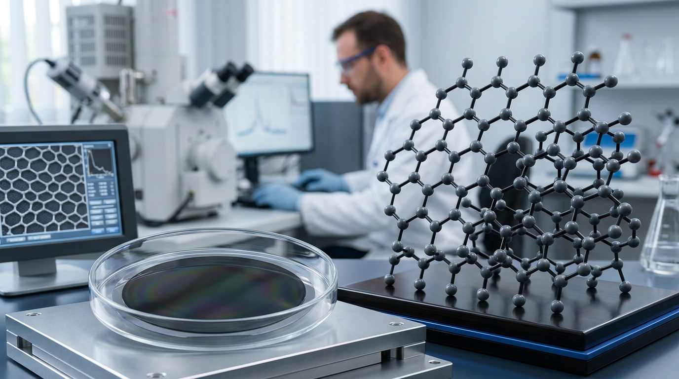
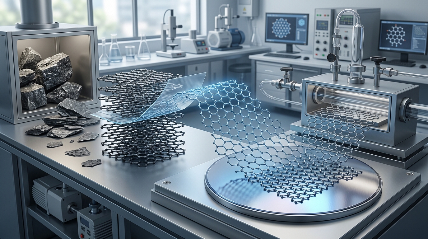
Turning graphite into graphene requires separating individual, single-atom-thick sheets of carbon from a stacked crystalline block. At the atomic level, graphite consists of countless layers of carbon atoms organized in a hexagonal lattice. While the carbon atoms within each individual plane form exceptionally strong sp2 covalent bonds, the adjacent layers are held together only by weak van der Waals forces. Converting graphite to graphene—a top-down manufacturing route—relies on supplying sufficient physical, chemical, or electrical energy to overcome these interlayer attractions without fracturing the two-dimensional carbon framework.
Because different applications demand varying levels of structural purity, flake size, and volume, scientists and industrial manufacturers employ several distinct exfoliation pathways. The primary methods include mechanical peeling, liquid-phase shear exfoliation, chemical oxidation-reduction, and electrochemical intercalation.
The Core Challenge: Van der Waals Attraction vs. In-Plane Strength
To understand how to turn graphite into graphene, one must look at the energy barrier separating the two forms. In natural flake graphite, the interlayer spacing between carbon sheets is approximately 0.335 nanometers. Overcoming the collective van der Waals binding energy requires roughly 60 to 300 millielectronvolts per carbon atom, depending on stacking order and local environmental conditions.
Applying stress perpendicular to the sheets or generating lateral shear forces allows these layers to slide apart. However, excessive perpendicular impact can shatter the planes into amorphous carbon dust rather than cleanly delaminating them. The goal of any successful exfoliation technique is to maximize delamination while minimizing tearing, basal-plane defect formation, and uncontrolled lateral fragmentation.
1. Mechanical Exfoliation: From Scotch Tape to High-Shear Mixing
Mechanical methods utilize direct physical force to cleave stacked carbon layers. Depending on the setup, mechanical exfoliation can yield pristine, defect-free single flakes for research or larger commercial volumes of few-layer sheets.
Micromechanical Cleavage
The landmark method that first isolated individual graphene monolayers in 2004 used common adhesive tape. In this process, graphite flakes are pressed between strips of tape and repeatedly pulled apart. Each peel halves the thickness of the remaining graphite until isolated single- and few-layer flakes remain adhered to the tape. Pressing the tape onto an oxidized silicon wafer transfers these flakes via local surface energy interactions.
While micromechanical cleavage produces atomically pristine graphene with exceptional charge carrier mobility and thermal conductivity, it is inherently a manual, low-throughput technique suitable only for fundamental laboratory physics.
Fluid Shear and Microfluidization
For scalable mechanical production, industrial processors use high-shear mixing and microfluidization. Graphite powders are suspended in a fluid medium and passed through narrow channels or rotor-stator generators at high velocities. The resulting fluid shear forces apply parallel sliding stress across the graphite platelets, stripping outer layers away one by one.
Microfluidization forces graphite suspensions through micro-channels under pressures exceeding 1,000 bar. The intense fluid cavitation and localized shear stress reliably produce unfunctionalized, few-layer graphene platelets without introducing chemical oxygen defects.
Ball Milling
Ball milling uses rotating or vibrating chambers filled with grinding balls (typically zirconia or stainless steel) and graphite powder. Dry ball milling often smashes the flakes, leading to high defect densities and edge damage. To mitigate this, processors utilize wet ball milling or planetary milling assisted by mild chemical additives. The liquid cushions normal impacts while promoting lateral friction, enabling continuous shear-induced delamination.
2. Liquid-Phase Exfoliation (LPE) via Sonication
Liquid-phase exfoliation disperses graphite powder into a liquid medium and uses acoustic energy to separate the sheets. High-power ultrasonic probes generate microscopic vacuum bubbles in the fluid—a phenomenon known as acoustic cavitation. When these bubbles collapse near the graphite surfaces, they produce localized shockwaves and high-velocity micro-jets that overcome interlayer adhesion.
Matching Surface Energy
A critical barrier in liquid-phase exfoliation is preventing the separated graphene sheets from immediately re-stacking. Carbon layers are naturally hydrophobic and will agglomerate if the liquid does not provide sufficient energetic stabilization.
To achieve stable suspensions, the surface tension of the solvent must closely match the surface energy of graphene (roughly 40 to 50 millijoules per square meter). Solvents such as N-methyl-2-pyrrolidone (NMP) and dimethylformamide (DMF) are highly effective at stabilizing individual flakes. Because these solvents carry high boiling points and toxicity concerns, water-surfactant mixtures (using sodium cholate, sodium dodecyl sulfate, or polymeric stabilizers) are widely used as safer, more manageable alternatives.
3. Chemical Exfoliation: The Graphene Oxide Route
Chemical oxidation followed by thermal or chemical reduction represents the highest-yield method for converting bulk graphite into dispersible two-dimensional sheets. This multi-step process alters the graphite structure chemically to facilitate separation.
Oxidation via Modified Hummers’ Method
The standard chemical route relies on the Hummers method or its modern variations. Bulk graphite reacts with strong oxidizing agents, typically a mixture of concentrated sulfuric acid, sodium nitrate, and potassium permanganate. As oxygen functional groups (such as epoxy, hydroxyl, and carboxyl groups) attach to the basal plane and edges, they push the interlayer spacing from 0.335 nanometers to more than 0.8 nanometers.
This increased spacing drastically weakens the interlayer van der Waals bonding and makes the material hydrophilic. Mild agitation or low-power sonication in water easily disperses the oxidized graphite into single-layer sheets of graphene oxide (GO).
Reduction to rGO
Graphene oxide is electrically insulating because the sp2 aromatic network is disrupted by sp3 hybridized carbon-oxygen bonds. To restore electrical and thermal properties, the material must undergo reduction, transforming into reduced graphene oxide (rGO). Reduction is accomplished through:
- Chemical reduction: Treating GO dispersions with reducing agents such as hydrazine hydrate, ascorbic acid (vitamin C), or sodium borohydride.
- Thermal reduction: Rapidly heating dried GO powder in an inert or reducing atmosphere (argon, nitrogen, or hydrogen) to flash-vaporize oxygen groups, creating localized pressure bursts that further separate the sheets.
- Hydrothermal or solvothermal treatment: Heating aqueous GO suspensions under elevated pressure in an autoclave.
Although reduction restores electrical conductivity, rGO retains residual oxygen groups and structural vacancies, meaning its performance characteristics differ from pristine, defect-free graphene.
4. Electrochemical Exfoliation
Electrochemical exfoliation provides a fast, continuous route that operates at ambient temperature without requiring toxic heavy oxidizers. A solid graphite rod, foil, or compressed pellet acts as an electrode submerged in an electrolyte solution.
When an electrical potential is applied, charged ions from the electrolyte migrate into the graphite interlayers—a process known as electrochemical intercalation. Once inside the lattice, these intercalated ions generate gas bubbles (such as sulfur dioxide, oxygen, or nitrogen oxides) through localized electrolysis. The expanding gas forces the graphite layers apart, releasing pristine to mildly oxidized few-layer graphene flakes directly into the bath.
Using anodic exfoliation (positive bias) typically introduces mild surface oxidation, facilitating stable water dispersion. Cathodic exfoliation (negative bias) uses non-oxidizing salts and organic solvents to produce high-purity, low-defect graphene with preserved electrical conductivity.
Comparison of Graphite-to-Graphene Exfoliation Methods
| Method | Primary Mechanism | Structural Quality | Scalability | Primary Output Form |
|---|---|---|---|---|
| Micromechanical Cleavage | Adhesive tape peel | Pristine; zero defects | Extremely low (research only) | Isolated single-layer flakes on substrates |
| Liquid-Phase Exfoliation (LPE) | Cavitation via ultrasound | High; minimal defects, small flake size | Medium to high | Liquid dispersions of few-layer graphene |
| Fluid Shear Exfoliation | Hydrodynamic shear stress | High; unfunctionalized sheets | Very high (continuous processing) | Graphene nanoplatelets and few-layer slurries |
| Chemical Oxidation (GO/rGO) | Acid intercalation & oxidation | Modified; residual vacancies & oxygen | Mass production scale | Powders, films, and aqueous solutions of GO/rGO |
| Electrochemical Exfoliation | Ionic intercalation & gas expansion | Moderate to high; controllable defects | High | Dispersible powders and conductive inks |
Understanding the Output: Graphene Types and Classifications
A common point of confusion when learning how to turn graphite into graphene is the distinction between single-layer sheets and multi-layer stacks. Standard international conventions categorize the resulting materials by their layer count and lateral dimensions:
- Monolayer Graphene: Exactly one layer of carbon atoms. It displays exceptional optical transparency, thermal conductivity, and electronic properties.
- Few-Layer Graphene (FLG): Stacks containing 2 to 10 carbon layers. FLG retains many unique 2D physical behaviors while offering higher physical robustness during material handling.
- Graphene Nanoplatelets (GNPs): Thicker particles typically ranging from 10 to several dozen layers, with thicknesses up to 100 nanometers. GNPs are less expensive to produce in bulk and provide substantial mechanical reinforcement and thermal conductivity in bulk composites.
Key Practical Challenges in Processing
Converting graphite into graphene in a laboratory is straightforward, but consistent, industrial-scale processing involves overcoming several engineering bottlenecks.
Preventing Re-Agglomeration
Graphene sheets exhibit high specific surface area (theoretically up to 2,630 square meters per gram). Thermodynamically, pristine sheets favor re-stacking into graphite to minimize surface energy. Maintaining individual sheets requires continuous stabilization using surfactants, covalent functionalization, or immediate incorporation into host matrices such as polymers, resins, or cement.
Controlling Lateral Size and Aspect Ratio
Intense sonication or aggressive milling can over-fragment graphene sheets, reducing their lateral dimensions from micrometers down to tens of nanometers. Smaller sheets increase the number of inter-flake boundaries in a conductive network, which raises electrical resistance. Balancing thickness reduction with lateral size retention is essential for electronic and conductive applications.
Purity and Chemical Residues
Chemical and liquid exfoliation routes require extensive downstream washing, centrifugation, and filtration. Residual sulfuric acid, manganese salts from Hummers’ method, or high-boiling-point solvents like NMP can degrade the performance of energy-storage electrodes or polymer composites if not thoroughly removed.
How Processors Measure Graphene Quality
To confirm that graphite has successfully transformed into graphene, materials scientists use specialized analytical tools:
- Raman Spectroscopy: The primary non-destructive tool for evaluating carbon structures. The intensity ratio of the D-band (around 1350 cm⁻¹) to the G-band (around 1580 cm⁻¹) indicates defect density, while the shape and position of the 2D-band (around 2700 cm⁻¹) reveal the exact number of stacked layers.
- Atomic Force Microscopy (AFM): Provides precise cross-sectional height profiles to confirm whether a flake is truly a single layer (approximately 0.4 to 1.0 nm apparent AFM thickness) or multi-layered.
- Transmission Electron Microscopy (TEM): Delivers high-resolution imaging of flake edges, allowing direct counting of atomic layers and verification of the hexagonal lattice integrity.
- X-ray Photoelectron Spectroscopy (XPS): Measures the carbon-to-oxygen (C/O) ratio, quantifying how effectively graphene oxide has been reduced back to an sp2 carbon network.
Matching the Exfoliation Method to the Application
No single conversion method is universally superior; the correct process depends entirely on the intended end use. Applications requiring maximum electrical conductivity and charge transport, such as transparent conductive films and advanced sensors, rely on low-defect electrochemical exfoliation or pristine fluid shear methods. Conversely, bulk structural composites, anti-corrosion coatings, concrete additives, and thermal greases frequently utilize reduced graphene oxide or graphene nanoplatelets, where high-volume production, low cost, and strong matrix compatibility outweigh the need for absolute crystal perfection.