Methods for Producing Graphene from Graphite
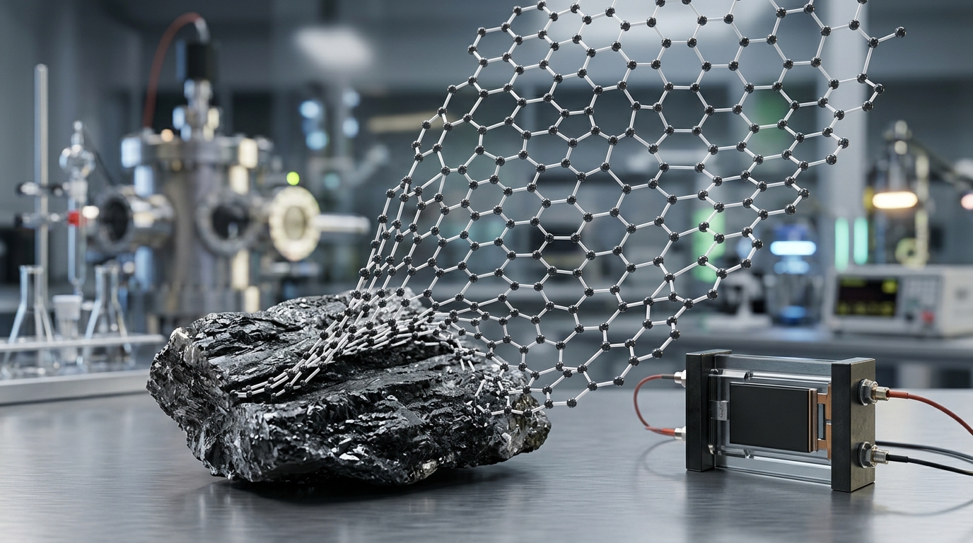
Extracting individual atomic layers of carbon from bulk graphite requires overcoming the van der Waals forces that hold stacked graphene sheets together. Graphite consists of millions of stacked sp²-hybridized carbon sheets spaced roughly 0.335 nanometers apart, held by an interlayer binding energy of approximately 60 to 70 milli-electronvolts per carbon atom. The primary methods for producing graphene from graphite rely on top-down processing, where physical shear, chemical intercalation, oxidation, or electrical bias overcome these cohesive forces to isolate single-layer, few-layer, or multi-layer graphene flakes.
Unlike bottom-up synthesis methods such as chemical vapor deposition (CVD)—which assemble carbon atoms into continuous sheets on metal substrates—top-down graphite processing produces discrete flakes, platelets, and powders. These particulate forms serve as critical additives for composites, thermal management interfaces, conductive coatings, energy storage electrodes, and functional lubricants. Choosing an exfoliation route involves navigating strict trade-offs between structural purity, throughput, flake dimensions, chemical defect density, and cost.
The Fundamental Physics of Graphite Exfoliation
Graphite possesses strong in-plane covalent carbon-carbon bonds paired with weak out-of-plane cohesive bonds. To separate these sheets without tearing them into amorphous carbon fragments, an applied force or chemical agent must deliver enough energy to exceed the interlayer adhesion while minimizing in-plane lattice damage.
Top-down isolation techniques approach this challenge through three primary physical and chemical pathways:
- Direct mechanical shear or cavitation: Applying lateral physical force to slide sheets apart or using acoustic shockwaves to pull them apart perpendicular to their basal planes.
- Intercalation and expansion: Inserting ionic or molecular species between graphite layers to increase the interlayer distance, drastically weakening the van der Waals attraction before complete delamination.
- Chemical functionalization: Oxidizing the basal plane to disrupt the aromatic network, generating repulsive electrostatic charges and hydrophilic properties that allow spontaneous dispersion in polar solvents.
Micromechanical Cleavage: The Benchmark Technique
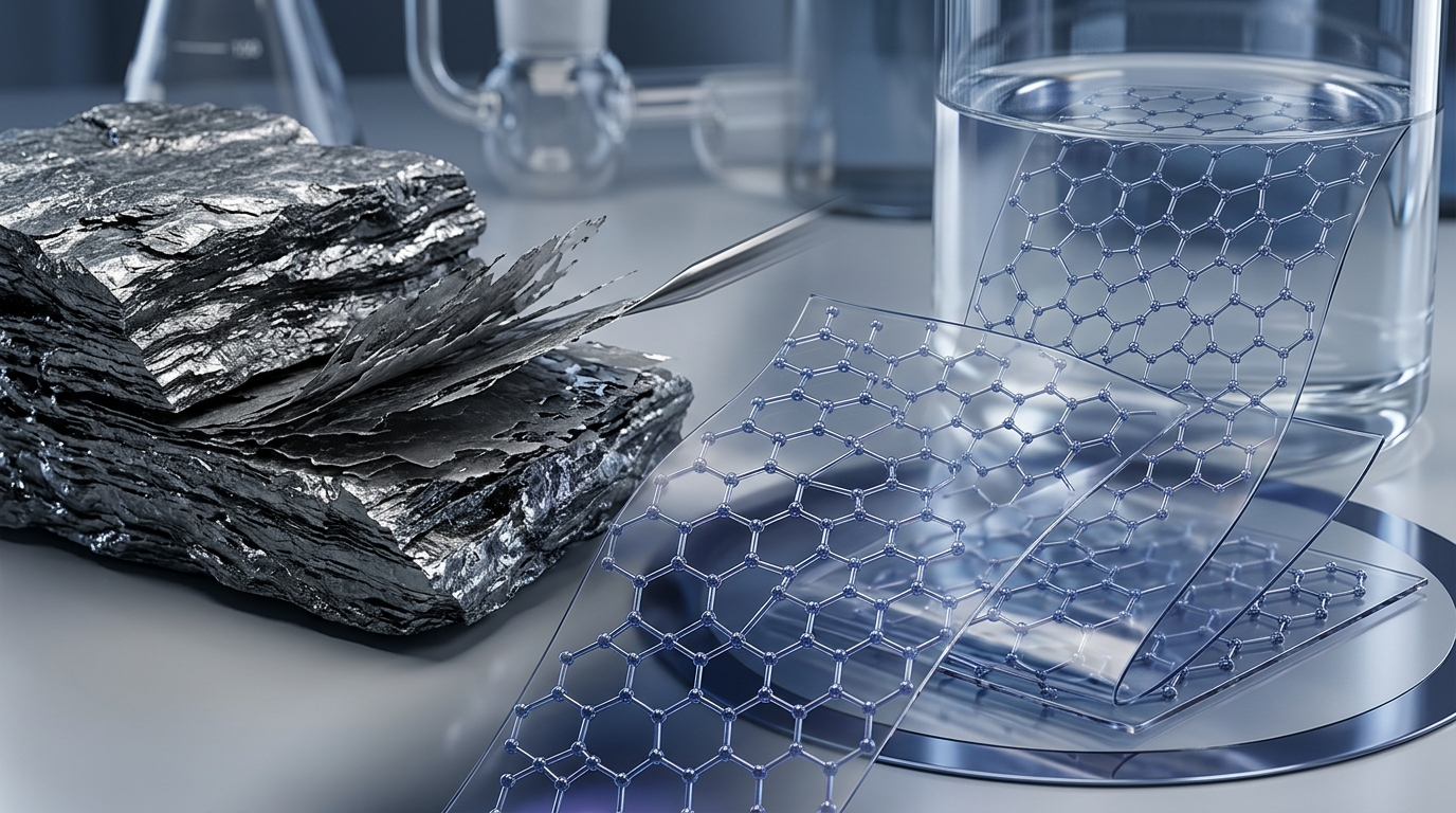
Micromechanical cleavage, commonly known as the Scotch tape method, was the technique used in 2004 to isolate and characterize single-layer graphene for the first time. The process uses an adhesive polymer tape applied to the surface of highly oriented pyrolytic graphite (HOPG) or natural graphite flakes.
When the tape is peeled away, the normal peel stress exceeds the interlayer cleavage energy of graphite, cleaving bulk crystals into thinner films. By repeatedly folding and peeling the adhesive tape, the graphite layers are thinned until individual monolayers adhere to the tape. Pressing the tape against an oxidized silicon wafer transfers pristine, single-crystal graphene flakes onto the substrate via surface adhesion.
Performance and Limitations: Micromechanical cleavage produces graphene of exceptional structural quality, displaying electron mobility exceeding 200,000 cm²/(V·s) and virtually zero crystallographic defects. However, the yield is microscopic, unpredictable, and completely unsuited for commercial manufacturing. It remains a laboratory benchmark for fundamental physics research, device prototyping, and scanning probe calibration.
Liquid-Phase Exfoliation (LPE)
Liquid-phase exfoliation separates pristine graphite flakes directly in a liquid medium without aggressive chemical oxidation. This technique preserves the intrinsic electrical and thermal properties of the sp² carbon lattice while producing scalable quantities of dispersion-ready graphene.
Solvent Matching and Ultrasonic Exfoliation
Ultrasonic exfoliation uses high-frequency acoustic waves to generate acoustic cavitation within a liquid suspension of graphite. The rapid formation and violent collapse of microbubbles produce localized shockwaves and microjets, exerting strong normal and shear forces on graphite particles.
To prevent the freshly peeled graphene sheets from immediately restacking, the surface energy of the solvent must closely match that of graphene (roughly 70 to 80 mJ/m²). Solvents like N-methyl-2-pyrrolidone (NMP) and dimethylformamide (DMF) minimize the net enthalpy of mixing, allowing stable colloidal suspensions. When using water, non-ionic or ionic surfactants (such as sodium cholate or sodium dodecyl sulfate) are added to coat the flakes and create steric or electrostatic repulsion.
High-Shear Mixing and Microfluidization
While sonication effectively cleaves sheets, prolonged acoustic energy often fragments large flakes into sub-micron debris. High-shear mixing routes graphite suspensions through narrow gaps between high-speed rotors and stators. The resulting hydrodynamic shear flow provides a controlled lateral sliding action that separates layers along the basal plane while preserving larger lateral flake dimensions.
Microfluidization advances this principle by forcing graphite slurries through microscopic interaction chambers at pressures reaching several thousand bar. The fluid split and re-impingement generate massive shear rates (exceeding 10&sup6; s&supmin;¹), yielding thin graphene nanoplatelets with high batch-to-batch consistency and relatively high throughput.
Chemical Oxidation-Reduction: The Graphene Oxide Route
The most widely deployed high-volume manufacturing route converts graphite into an intermediate material called graphene oxide (GO), followed by reduction to yield reduced graphene oxide (rGO).
Oxidation via Modified Hummers' Method
Graphite flakes are treated with strong oxidizing agents, typically concentrated sulfuric acid (H&sub2;SO&sub4;), sodium nitrate (NaNO&sub3;), and potassium permanganate (KMnO&sub4;). The oxidizing agents intercalate between the graphite layers and covalently attach oxygen-containing functional groups—primarily epoxy (-O-) and hydroxyl (-OH) groups on the basal plane, along with carboxylic acid (-COOH) groups at the edges.
This functionalization dramatically alters the material:
- Interlayer spacing increases from 0.335 nm to between 0.7 and 1.2 nm depending on humidity.
- The material transitions from hydrophobic and electrically conductive to highly hydrophilic and electrically insulating.
- The heavily oxidized graphite disperses almost spontaneously into single-layer GO sheets in water under mild stirring or brief sonication.
Reduction to rGO
Because GO is non-conductive and structurally disordered due to sp³ carbon defects, oxygen groups must be removed to restore electrical and thermal pathways. This is achieved through several reduction mechanisms:
- Chemical Reduction: Exposing GO dispersions to reducing agents like hydrazine hydrate, ascorbic acid (vitamin C), or sodium borohydride restores significant sp² network conjugation.
- Thermal Annealing: Heating dry GO rapidly above 800°C in an inert or reducing atmosphere (argon, nitrogen, or hydrogen) vaporizes oxygen species as CO and CO&sub2; gas, simultaneously expanding and reducing the material.
- Hydrothermal/Photothermal Processing: High-pressure, high-temperature water treatment or intense pulsed light systems reduce GO films rapidly without toxic chemical consumables.
Although rGO recovers substantial electrical conductivity, permanent topological lattice defects, carbon vacancies, and residual oxygen (typically 5% to 15% atomic oxygen) prevent it from matching the performance of pristine, unoxidized graphene.
Electrochemical Exfoliation
Electrochemical exfoliation offers a rapid, low-temperature, and environmentally friendly alternative to traditional wet-chemical oxidation. This method uses a bulk graphite electrode immersed in an electrolyte bath under an applied direct-current voltage.
Anodic Exfoliation
When graphite serves as the positive electrode (anode) in an aqueous sulfate-based electrolyte (such as ammonium sulfate, (NH&sub4;)&sub2;SO&sub4;), negative sulfate ions (SO&sub4;²&supmin;) and water molecules migrate into the graphite interlayer galleries. The applied potential electrolyzes the intercalated water, releasing localized oxygen and sulfur dioxide gases:
2H&sub2;O → O&sub2; + 4H&spplus; + 4e&supmin;
The sudden gaseous expansion pushes the carbon layers apart, causing the graphite anode to shed thin, low-defect graphene flakes directly into the solution. Anodic exfoliation introduces only mild oxidation (typically less than 10% oxygen content), yielding higher conductivity than rGO without demanding toxic reagents.
Cathodic Exfoliation
When graphite is biased as the negative electrode (cathode) in non-aqueous electrolytes containing small cations—such as lithium ions or tetraalkylammonium salts in propylene carbonate—cations intercalate without triggering oxygen evolution. Subsequent dispersion in solvent or brief sonication delaminates the expanded graphite into unoxidized, pristine graphene flakes, completely avoiding basal-plane oxidation.
Mechanochemical and Ball Milling Methods
Mechanochemical ball milling utilizes mechanical impact and friction inside a rotating vial containing milling media (such as zirconia or steel balls) to delaminate dry or wet graphite powder.
To avoid crushing the graphite into useless amorphous carbon, non-destructive ball milling employs specific chemical additives:
- Dry milling with solid salts or dry ice: Milling graphite with solid carbon dioxide or potassium hydroxide causes edge-selective covalent functionalization. The impact shears the edges, attaching functional groups (such as -COOH) while leaving the central basal planes undamaged and fully aromatic.
- Wet planetary milling: Using low-viscosity liquid carriers and surfactant solutions converts vertical impact forces into lateral sliding friction, promoting shear exfoliation over compressive fragmentation.
This approach produces high-concentration dispersions and easily functionalized powders suitable for direct compounding into thermoplastics, thermosets, and battery slurries.
Comparison of Graphite-to-Graphene Production Methods
The following table outlines how top-down production methods differ across critical physical, operational, and material parameters:
| Production Method | Typical Layer Count | Defect Level (ID/IG) | Throughput Potential | Primary Target Applications |
|---|---|---|---|---|
| Mechanical Cleavage | 1 (Monolayer) | Near Zero (< 0.05) | Microscopic only | Fundamental physics, advanced metrology |
| Liquid-Phase (LPE) | 1 to 5 layers | Low (0.1 to 0.3) | Moderate to High | Conductive inks, thermal coatings |
| Oxidation/Reduction (rGO) | 1 to 3 layers | High (0.8 to 1.5) | Very High (Tons) | Composite additives, water filtration, supercapacitors |
| Electrochemical | 2 to 8 layers | Low to Moderate (0.2 to 0.6) | High | Battery anodes, conductive masterbatches |
| Mechanochemical / Milling | 3 to 10+ layers (GNPs) | Edge-localized defects | Very High | Polymer reinforcement, concrete, lubricants |
Material Evaluation and Quality Metrics
Because top-down methods produce heterogeneous mixtures rather than uniform macroscopic sheets, downstream performance depends on rigorous quality metrics. The following characterization techniques determine the utility of graphene derived from graphite:
Raman Spectroscopy
Raman spectroscopy serves as the primary non-destructive tool for evaluating graphite-derived flakes. The spectrum reveals three primary signatures:
- G band (~1580 cm&supmin;¹): Represents the in-plane vibrational mode of intact sp² hybridized carbon networks.
- D band (~1350 cm&supmin;¹): Measures symmetry-breaking structural defects, lattice vacancies, and edge functionalization. The intensity ratio of the D band to the G band (ID/IG) quantifies crystallographic defect density.
- 2D band (~2700 cm&supmin;¹): Highly sensitive to layer stacking. A sharp, symmetric single Lorentzian 2D peak indicates monolayer graphene, while broader, shifted, multi-component peaks denote few-layer or multi-layer graphite.
Morphological Analysis via AFM and TEM
Atomic Force Microscopy (AFM) provides precise topographic cross-sections, measuring flake thickness down to sub-nanometer levels to confirm monolayer (apparent height ~0.8 to 1.0 nm on silicon substrates due to chemical contrast) versus few-layer status. Transmission Electron Microscopy (TEM), along with selected area electron diffraction (SAED), inspects edge folding, crystallographic lattice alignment, and lateral dimensions.
Commercial Processing and Integration Realities
Scaling up graphene extraction from graphite involves practical chemical engineering challenges that dictate processing economics:
Washing and Solvent Removal: Methods like Hummers’ oxidation and liquid-phase exfoliation require extensive post-processing. Removing toxic solvents (like NMP) or residual acid salts demands multi-stage cross-flow membrane filtration, high-speed centrifugation, and neutral water washing. Incomplete surfactant or solvent removal creates insulating barriers around flakes, severely degrading electrical transport in downstream applications.
Flake Restacking (Agglomeration): Once isolated in dispersion, individual graphene sheets exhibit a strong thermodynamic tendency to agglomerate back into graphite due to cohesive pi-pi stacking. Maintaining stable suspensions requires careful formulation with specific polymer stabilizers, surface functionalization, or immediate dispersion into host matrices via masterbatch compounding.
Classification Standards: According to international standards (such as ISO/TS 80004-13), isolated carbon materials are classified based on layer count:
- Graphene (monolayer): Exactly 1 carbon layer.
- Few-layer graphene (FLG): 2 to 10 carbon layers.
- Graphene nanoplatelets (GNPs): Thickness between 1 nm and 3 nm (or up to 100 nm depending on specification), with lateral dimensions significantly larger than thickness.
Materials containing more than 10 carbon layers lose the distinct electronic and mechanical properties unique to two-dimensional confinement, behaving instead like ultrafine graphite flakes.
Selecting the Optimal Production Route
No single graphite exfoliation method fulfills every commercial and technical requirement. Applications demanding high electrical conductivity and transparent optical performance (such as flexible conductive films and specialized sensors) favor low-defect liquid-phase or electrochemical exfoliation. Conversely, bulk structural applications—including mechanical reinforcement of polymers, concrete strengthening, thermal dissipation greases, and high-energy battery electrode additives—are dominated by cost-effective, high-yield graphene oxide reduction and scalable mechanochemical shear milling.