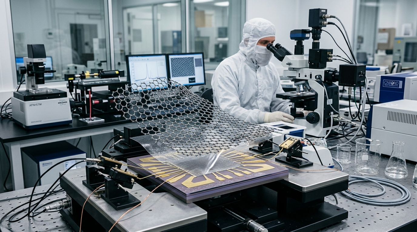
How Is Graphene Made?
Graphene, a single layer of carbon atoms arranged in a two-dimensional honeycomb lattice, possesses extraordinary electrical conductivity, mechanical strength, and thermal properties. However, answering the question of how is graphene made requires understanding that there is no single, universal manufacturing technique. Instead, multiple distinct synthesis routes exist, each tailored to produce specific forms of graphene—ranging from ultra-pure monolayer sheets for quantum electronics to high-volume graphene nanoplatelets for composite materials.
All graphene production techniques fall into two overarching thermodynamic and mechanical philosophies: top-down methods, which strip graphite down to individual atomic layers, and bottom-up methods, which assemble graphene atom-by-atom from carbon-containing gas or molecular precursors.
The Two Manufacturing Paradigms: Top-Down vs. Bottom-Up
The choice of production route fundamentally dictates the purity, defect density, flake dimensions, and economic viability of the resulting material.
- Top-Down Methods: These techniques start with naturally occurring or synthetic bulk graphite, which consists of millions of stacked graphene sheets held together by weak van der Waals forces. Top-down processing uses mechanical shear, chemical oxidation, or ultrasonic energy to overcome these interlayer forces and separate the sheets. These methods excel at producing large volumes of graphene flakes, platelets, and powders at lower cost, though often with higher defect rates.
- Bottom-Up Methods: These techniques build the two-dimensional lattice from the ground up using carbonaceous precursors such as methane, ethylene, or solid carbon sources. Carbon atoms are dissociated and reconstituted on a catalytic substrate or crystalline template. Bottom-up synthesis produces large-area, continuous, high-purity monolayer films ideal for semiconductor devices and transparent conductors, but at higher costs and lower volumetric yields.
1. Mechanical Exfoliation (The Micromechanical Cleavage Method)
Historically, mechanical exfoliation is the method that enabled the initial isolation and characterization of single-layer graphene in 2004. Often referred to as the “Scotch tape method,” it remains a cornerstone of fundamental scientific research.
How the Process Works
Mechanical exfoliation relies on normal or shear forces to overcome the interlayer van der Waals bonding energy of graphite (approximately 300 meV/nm²):
- An adhesive tape is applied to the surface of a piece of highly oriented pyrolytic graphite (HOPG) or high-purity natural graphite flakes.
- Peeling the tape pulls away multi-layer flakes of graphite.
- The tape is folded and peeled repeatedly, continually dividing the cleaved flakes into thinner layers.
- The tape is pressed onto a target substrate (typically silicon with a carefully tuned silicon dioxide layer, such as 300 nm SiO₂) and peeled away, leaving isolated single- and few-layer graphene flakes adhering to the substrate through van der Waals interactions.
Strengths and Limitations
Mechanical cleavage produces pristine, defect-free monolayer graphene with native sp² hybridization, preserving record-high electron mobility (exceeding 200,000 cm²/V·s) and thermal performance. However, because the process produces microscopic flakes (rarely larger than tens of micrometers) at random locations with near-zero throughput, it cannot be scaled for industrial manufacturing. Its utility is largely restricted to laboratory device prototyping and fundamental physics exploration.
2. Chemical Vapor Deposition (CVD)
Chemical Vapor Deposition is the leading bottom-up method for manufacturing large-area, continuous, high-quality graphene films. It is the primary route for transparent conducting electrodes, flexible electronics, and advanced sensor platforms.
The Catalytic Reaction Mechanism
In thermal CVD, a metal catalyst substrate is placed in a high-temperature furnace (typically 800°C to 1050°C) under low pressure or atmospheric conditions:
- Precursor Introduction: A gaseous carbon feedstock, typically methane (CH₄), is introduced alongside carrier gases such as hydrogen (H₂) and argon (Ar).
- Catalytic Decomposition: The transition metal substrate catalyzes the cracking of methane at elevated temperatures, stripping hydrogen atoms and releasing active carbon species onto the surface.
- Substrate Dynamics (Copper vs. Nickel): The choice of metal catalyst fundamentally alters how the graphene forms:
- Copper (Cu): Carbon has extremely low solubility in copper. As a result, graphene growth on copper is a surface-mediated, self-limiting process. Once a continuous monolayer covers the copper surface, the catalytic reaction ceases, making copper the premier substrate for uniform single-layer graphene.
- Nickel (Ni): Carbon exhibits high solubility in nickel at elevated temperatures. Carbon dissolves into the bulk metal and precipitates back to the surface during cooling. Because precipitation rates are difficult to control uniformly, nickel typically yields multi-layer graphene with varying thickness.
Substrate Transfer Challenges
Growing graphene on copper foil is only the first step; most electronic applications require the graphene to sit on an insulating dielectric, such as silicon dioxide or quartz. Transferring a one-atom-thick film without introducing tears, wrinkles, or chemical contamination is a major engineering hurdle.
The traditional approach involves spin-coating a sacrificial polymer support layer—such as poly(methyl methacrylate) (PMMA)—over the graphene, chemically etching the underlying metal foil in an acid bath (e.g., ferric chloride or ammonium persulfate), placing the floating PMMA/graphene stack onto the target substrate, and dissolving the PMMA with solvents like acetone. Modern industrial approaches utilize continuous roll-to-roll dry delamination, which mechanically separates the graphene using adhesive carrier films, allowing the metal substrate to be recycled.
3. Liquid-Phase Exfoliation (LPE)
Liquid-Phase Exfoliation is a top-down method engineered to produce scalable quantities of few-layer graphene and graphene nanoplatelets (GNPs) suspended in liquid media. It is widely used for producing conductive inks, composite additives, energy storage slurry components, and thermal dissipation coatings.
The Exfoliation Mechanism
LPE relies on introducing mechanical energy into a liquid suspension of graphite to overcome the interlayer cohesion:
- Ultrasonication: High-power ultrasound waves generate acoustic cavitation bubbles in the liquid. The violent collapse of these microbubbles produces localized shockwaves and microjets that exert high shear forces on graphite particles, cleaving them into thin flakes.
- High-Shear Mixing: High-speed rotor-stator mixers generate localized shear rates exceeding 10⁴ s⁻¹, sliding the graphene layers apart without excessive fragmenting of their lateral dimensions.
- Microfluidization: Graphite suspensions are forced through micro-channels under pressures exceeding 1,000 bar, utilizing intense shear and collisions to delaminate flakes at high volumetric throughputs.
Solvent Selection and Stabilization
A central challenge in LPE is preventing the exfoliated graphene sheets from re-stacking due to van der Waals attraction. To prevent re-agglomeration, the surface energy of the solvent must closely match the surface energy of graphite (approximately 68–70 mJ/m²):
- Organic Solvents: Solvents like N-Methyl-2-pyrrolidone (NMP) and Dimethylformamide (DMF) naturally stabilize graphene sheets, though they are costly, toxic, and feature high boiling points that complicate post-processing.
- Aqueous Surfactant Solutions: Water can be used when paired with ionic or non-ionic surfactants (such as sodium cholate or sodium dodecyl sulfate). The surfactant molecules adsorb onto the graphene surface, providing electrostatic or steric repulsion that keeps the flakes dispersed.
4. Chemical Synthesis: Graphene Oxide (GO) and Reduced Graphene Oxide (rGO)
The chemical oxidation and subsequent reduction of graphite provides a cost-effective, highly scalable chemical pathway to bulk graphene derivatives. While the resulting material contains more structural defects than pristine CVD graphene, its processability makes it ideal for water filtration, coatings, and energy storage devices.
Step 1: Synthesis of Graphene Oxide (The Hummers Method)
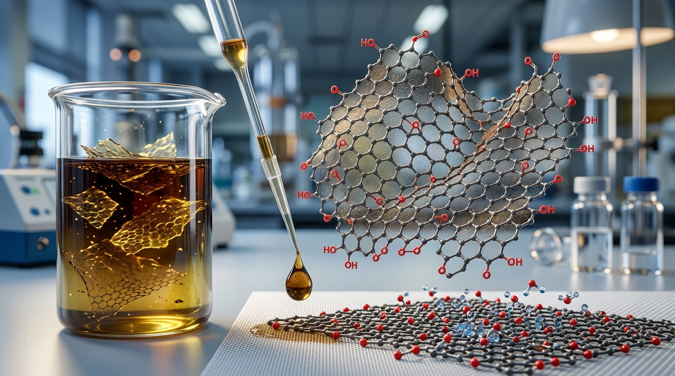
Graphene oxide is synthesized by exposing natural graphite flakes to harsh chemical oxidants. The classic Hummers method, along with its modern modified iterations, uses a mixture of concentrated sulfuric acid (H₂SO₄), sodium nitrate (NaNO₃), and potassium permanganate (KMnO₄):
- The chemical reaction intercalates oxygen-containing functional groups into the graphitic lattice, primarily epoxy (-O-) and hydroxyl (-OH) groups on the basal planes, along with carboxyl (-COOH) and carbonyl (=O) groups at the sheet edges.
- These functional groups increase the interlayer spacing from 0.34 nm (in graphite) to over 0.8 nm, weakening the interlayer bonding.
- The oxygen groups render the material strongly hydrophilic, enabling complete, spontaneous exfoliation into single-layer Graphene Oxide sheets upon gentle agitation in water.
- Trade-off: The oxidation disrupts the native sp² conjugated network, converting large regions to tetrahedral sp³ carbon, which destroys electrical conductivity and renders GO an electrical insulator.
Step 2: Reduction to rGO
To restore electrical and thermal conductivity, the oxygen functional groups must be removed through reduction, converting GO into reduced Graphene Oxide (rGO). Three primary reduction pathways are used:
- Chemical Reduction: Exposing GO suspensions to reducing agents such as hydrazine monohydrate, sodium borohydride, or safer green alternatives like ascorbic acid (Vitamin C).
- Thermal Reduction: Rapidly heating dried GO in an inert or reducing atmosphere (argon, nitrogen, or hydrogen) at temperatures between 200°C and 1000°C. The rapid expansion and release of trapped gases (CO, CO₂, H₂O) exfoliates and reduces the material simultaneously.
- Electrochemical and Photothermal Reduction: Using laser pulses, flash lamps, or direct electrode potentials to strip oxygen groups without requiring hazardous chemical reagents.
While reduction restores substantial conductivity, residual oxygen groups and vacancy defects remain within the lattice. Consequently, rGO functions as a distinct material rather than a direct equivalent to pristine graphene.
5. Alternative and Emerging Manufacturing Innovations
As research advances, novel synthesis techniques continue to emerge, addressing specific trade-offs between cost, speed, scalability, and substrate compatibility.
Epitaxial Growth on Silicon Carbide (SiC)
This bottom-up method involves heating single-crystal silicon carbide wafers to extreme temperatures (above 1300°C–1400°C) in an ultra-high vacuum or argon environment. The silicon atoms selectively sublimate from the surface due to their higher vapor pressure, leaving behind excess carbon atoms that self-assemble into continuous, epitaxial graphene layers. This process produces high-quality graphene directly on a semi-insulating wafer without requiring transfer steps, making it well-suited for high-frequency radio-frequency (RF) transistors.
Flash Joule Heating (FJH)
Developed as an ultra-fast, solvent-free synthesis method, Flash Joule Heating passes an intense electrical pulse through solid, low-cost carbonaceous materials (such as biochar, mixed plastic waste, or petroleum coke). The pulse raises the material’s temperature above 3000 K within milliseconds. At these extreme temperatures, non-carbon elements instantly volatilize, and the remaining carbon atoms reassemble into “turbostratic” graphene—sheets that are rotational misaligned, preventing tight stacking and facilitating easy dispersion.
Laser-Induced Graphene (LIG)
Laser-Induced Graphene is a single-step, photothermal synthesis technique. A standard CO₂ or infrared laser scribes patterns onto commercial polyimide films or renewable carbon substrates (such as wood or lignin) under ambient conditions. The localized photothermal energy breaks chemical bonds, carbonizing the surface and producing a porous, 3D network of few-layer graphene. LIG is widely explored for on-chip micro-supercapacitors, flexible biosensors, and wearable electronics.
Comparative Analysis of Graphene Production Methods
Choosing the right synthesis method requires matching the structural quality, form factor, and production economics to the intended end-use:
| Synthesis Method | Structural Quality | Scalability & Yield | Relative Cost | Primary Target Applications |
|---|---|---|---|---|
| Mechanical Exfoliation | Pristine (Lowest defects, highest mobility) | Very Low (Microscopic flakes) | High (Labor-intensive) | Fundamental physics research, prototype electronics |
| Chemical Vapor Deposition (CVD) | Very High (Large-area continuous monolayer) | Moderate to High (Area-based) | Moderate to High | Optoelectronics, touchscreens, high-frequency transistors, sensors |
| Liquid-Phase Exfoliation (LPE) | Moderate to High (Few defects, small lateral size) | High (Liters/kilograms of dispersion) | Moderate | Conductive inks, composite masterbatches, thermal pastes |
| Oxidation & Reduction (GO / rGO) | Moderate to Low (Residual defects & oxygen groups) | Very High (Industrial bulk powders/liquids) | Low | Energy storage (batteries/supercapacitors), water filtration membranes, coatings |
| Epitaxial Growth on SiC | High (Uniform wafer-scale layers) | Low to Moderate (Wafer size limited) | Very High (Substrate cost) | High-frequency telecommunications, metrology standards |
| Flash Joule Heating (FJH) | Moderate (Turbostratic flakes) | High to Very High (Tons potential) | Very Low | Structural composites (concrete, asphalt, polymers) |
Summary: Matching Synthesis to Application
There is no singular answer to how graphene is made because “graphene” encompasses a family of two-dimensional materials with varying layer counts, flake geometries, and chemical purities. When continuous, ultra-pure sheets are required for next-generation computing or optoelectronic devices, bottom-up CVD and epitaxial growth serve as the benchmark routes. Conversely, when structural reinforcement, electrical conductivity in battery electrodes, or mass-produced functional inks are required, top-down approaches such as liquid-phase exfoliation, GO/rGO chemical reduction, and flash synthesis provide the necessary volumetric scalability and cost-efficiency.