How to Make Graphene?
Graphene can be synthesized through two foundational approaches: top-down methods, which peel or separate individual atomic layers from bulk graphite, and bottom-up methods, which assemble carbon atoms directly from gaseous or solid carbon precursors. The chosen synthesis pathway dictates the resulting material’s crystal quality, electrical performance, layer count, flake size, and production volume.
Understanding how to make graphene requires balancing purity against scalability. While atomic monolayers with pristine structural lattices are necessary for advanced electronic and quantum devices, industrial-scale bulk composites, conductive inks, and coatings rely on high-throughput chemical or mechanical exfoliation processes.
Top-Down vs. Bottom-Up Synthesis Approaches
Every method for producing graphene falls within one of two thermodynamic and structural paradigms:
- Top-Down Synthesis (Exfoliation): Bulk graphite consists of stacked graphene sheets held together by weak van der Waals forces with an interlayer spacing of approximately 0.335 nanometers. Top-down methods overcome these interlayer forces using mechanical shear, acoustic cavitation, chemical oxidation, or electrochemical intercalation. The primary objective is to isolate single- to few-layer sheets without introducing permanent structural defects into the sp2-hybridized carbon network.
- Bottom-Up Synthesis (Direct Growth): Rather than breaking down bulk carbon, bottom-up processes build graphene atom by atom. Gaseous hydrocarbons (such as methane, ethylene, or acetylene) or solid carbon feedstocks are decomposed at high temperatures or catalyzed on metal substrates, causing carbon atoms to self-assemble into continuous hexagonal networks. This route produces large-area, high-crystallinity continuous films.
Mechanical Exfoliation: The Cleavage Method
Historically developed to isolate the first verifiable single layers of graphene in 2004, mechanical cleavage (commonly known as the Scotch tape method) remains the gold standard for producing pristine, defect-free graphene for fundamental scientific research.
Step-by-Step Laboratory Process
- Substrate Preparation: A silicon wafer coated with a precisely thermally grown silicon dioxide (SiO2) layer (typically 90 nm or 300 nm thick) is cleaned using an oxygen plasma or piranha solution to remove organic contaminants. The specific oxide thickness is crucial because it creates optical interference that makes individual monolayer flakes visible under a standard optical microscope.
- Adhesive Peeling: A flake of natural or Highly Oriented Pyrolytic Graphite (HOPG) is placed onto low-tack adhesive tape. The tape is folded and peeled apart multiple times to split the graphite into progressively thinner sheets.
- Transfer to Substrate: The tape bearing thin graphite flakes is pressed firmly against the prepared SiO2/Si substrate. Controlled pressure is applied to maximize contact area.
- Slow Separation: The adhesive tape is carefully peeled away from the substrate at a shallow angle. Residual van der Waals forces between the graphene and the silicon dioxide surface exceed the adhesion between the outer graphene layer and the tape, leaving isolated single-layer, bilayer, and multi-layer flakes on the substrate.
Laboratory Utility and Practical Limits
Mechanically exfoliated graphene exhibits unmatched carrier mobility (exceeding 200,000 cm2/V·s at low temperatures) and near-zero D-band defect peaks in Raman spectroscopy. However, the process is completely stochastic: flake dimensions are typically small (10 to 50 micrometers), spatial distribution is random, and throughput is restricted to individual manual flakes. It is strictly a discovery and prototyping tool, unsuitable for mass manufacturing.
Chemical Vapor Deposition (CVD): High-Quality Monolayer Growth
Chemical Vapor Deposition (CVD) is the most widely adopted bottom-up method for synthesizing large-area, continuous, high-crystallinity graphene films for electronics, photonics, and transparent conductive membranes.
The CVD Mechanism on Catalytic Foils
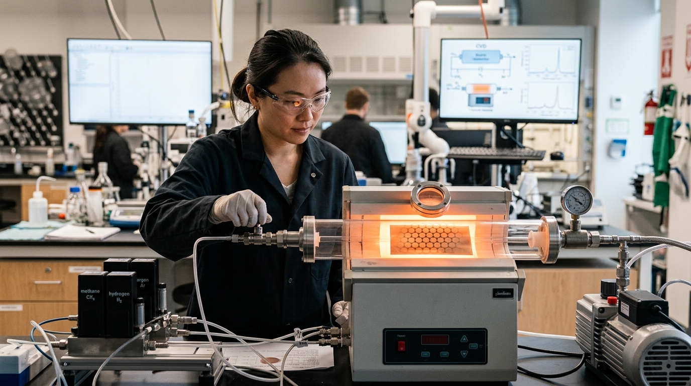
CVD growth typically utilizes transition metal substrates, most commonly polycrystalline copper (Cu) or nickel (Ni) foil, inside a high-temperature tube furnace (900°C to 1,050°C).
- Copper-Catalyzed Growth (Surface-Mediated): Copper has an exceptionally low carbon solubility. When a hydrocarbon gas like methane (CH4) mixed with hydrogen (H2) passes over heated copper foil, the copper catalyzes the dehydrogenation of methane. Because carbon cannot readily dissolve into the copper lattice, graphene nucleates directly on the copper surface. Once a complete monolayer covers the copper, the catalytic effect is shut off, making copper-based CVD naturally self-limiting to single layers.
- Nickel-Catalyzed Growth (Dissolution-Precipitation): Nickel has a high carbon solubility at elevated temperatures. Carbon atoms dissolve into the nickel bulk during exposure to the hydrocarbon gas. As the furnace cools, the solubility drops, forcing carbon atoms to precipitate out onto the surface. Controlling cooling rates to achieve uniform monolayers on nickel is significantly more difficult, often resulting in heterogeneous multi-layer graphene.
CVD Step-by-Step Procedure
- Substrate Annealing: Copper foil is heated under a reducing atmosphere (Ar/H2) to clean native oxides, enlarge metallic grain sizes, and smooth the surface morphology.
- Precursor Introduction: Methane is introduced at low pressure (LPCVD) or ambient pressure (APCVD) for a duration ranging from 5 to 30 minutes, initiating nucleation and domain coalescence into a continuous film.
- Controlled Cooling: The furnace is cooled rapidly to preserve domain uniformity and prevent secondary segregation.
- Film Transfer: Because the graphene resides on metal, it must be transferred to an insulating substrate. A support polymer (such as Poly(methyl methacrylate), or PMMA) is spin-coated over the graphene. The underlying copper is chemically etched away using an iron(III) chloride (FeCl3) or ammonium persulfate solution. The floating PMMA/graphene membrane is rinsed in deionized water, transferred onto the target substrate (e.g., quartz, SiO2, PET), and the PMMA is subsequently dissolved with acetone.
Liquid-Phase Exfoliation and Graphite Oxide Reduction
When high volumes of material are required—such as for conductive inks, energy storage, structural composites, and thermal dissipation—liquid-phase processing of graphite is the primary commercial route.
The Modified Hummers Method and Reduced Graphene Oxide (rGO)
Directly converting graphite into dispersible graphene flakes often proceeds through chemical functionalization to disrupt the strong interlayer bonding:
- Oxidation (Graphite to Graphite Oxide): Graphite powder is treated with strong oxidizers, typically concentrated sulfuric acid (H2SO4), sodium nitrate (NaNO3), and potassium permanganate (KMnO4), maintained under strict temperature control. This reaction intercalates oxygen-containing functional groups (epoxide, hydroxyl, carbonyl, and carboxyl) into the basal planes and edges.
- Exfoliation (Graphene Oxide – GO): The functional groups expand the interlayer spacing and render the sheets hydrophilic. Gentle sonication or mechanical stirring in water readily exfoliates the graphite oxide into single-layer Graphene Oxide (GO) suspensions.
- Reduction (GO to rGO): Graphene oxide is an electrical insulator due to disrupted sp2 hybridization. To restore electrical and thermal conductivity, oxygen functional groups must be removed. This is achieved through:
- Chemical Reduction: Treating the suspension with reducing agents like hydrazine hydrate, sodium borohydride, or safer alternatives such as L-ascorbic acid (Vitamin C).
- Thermal Reduction: Exposing dried GO powder to rapid thermal shock (typically 800°C to 1,050°C) under vacuum or inert atmosphere, or through flash optical irradiation.
Reduced graphene oxide (rGO) recovers much of its electrical conductivity, though it permanently retains residual structural vacancies, topological defects, and oxygen-containing functional groups compared to pristine graphene.
Direct Liquid-Phase Exfoliation (LPE)
To avoid chemical oxidation and preserve the pristine crystal lattice, graphite can be exfoliated directly in liquids using acoustic or fluid-dynamic energy:
- Solvent-Assisted Exfoliation: Graphite is dispersed in specific organic solvents whose surface energy closely matches that of graphene (approx. 70–80 mJ/m2), such as N-Methyl-2-pyrrolidone (NMP) or Dimethylformamide (DMF). High-power ultrasonic tip sonication generates cavitation bubbles that collapse against graphite flakes, overcoming van der Waals forces.
- Surfactant-Assisted Aqueous Exfoliation: Graphite is processed in water using ionic or non-ionic surfactants (such as sodium dodecyl sulfate, SDS) to prevent re-aggregation.
- High-Shear Mixing: Rotor-stator mixers apply intense hydrodynamic shear rates (>104 s-1) to slide graphite layers apart without pulverizing them, offering higher volume yields than sonication.
Modern Scalable Synthesis Methods
Emerging manufacturing technologies bypass wet-chemical etching and prolonged furnace cycles, producing functional graphene directly from low-cost carbon precursors.
Flash Joule Heating (FJH)
Flash Joule Heating converts virtually any carbonaceous material (metallurgical coke, biochar, carbon black, mixed plastic waste) into turbostratic graphene within milliseconds. An ultra-high current electrical discharge (capacitive discharge pulse) passes directly through the resistive carbon sample, raising the internal temperature above 3,000 K (approx. 2,727°C) in less than 100 milliseconds.
At this extreme temperature, all non-carbon elements sublimate rapidly, and the remaining carbon atoms rearrange into thermodynamically stable graphene sheets. Because the cooling rate is exceptionally high, the sheets form in a turbostratic orientation—meaning adjacent layers are misaligned and lack regular AB (Bernal) stacking. This rotational disorder makes flash graphene significantly easier to disperse in solvents and polymer matrices without aggressive sonication.
Laser-Induced Graphene (LIG)
Laser-Induced Graphene is a single-step, photothermal conversion process that produces porous, three-dimensional graphene foam directly on commercial polymer substrates. A standard computer-controlled CO2 or fiber laser scans across a polyimide (Kapton) sheet under ambient atmospheric conditions.
The local thermal energy generated by the laser absorption breaks the chemical bonds (C-O, C=O, and N-C) within the polyimide, releasing volatile gases and leaving behind an interconnected, highly conductive 3D network of few-layer graphene flakes. LIG is particularly useful for rapid direct-write patterning of flexible sensors, micro-supercapacitor electrodes, and wearable electronics without requiring cleanroom facilities or physical masks.
Comparison of Graphene Synthesis Methods
Each synthesis route involves distinct engineering trade-offs regarding material purity, mechanical throughput, and processing cost:
| Synthesis Method | Crystal Quality | Typical Flake/Sheet Size | Yield / Throughput | Relative Cost | Primary Form Factor |
|---|---|---|---|---|---|
| Mechanical Exfoliation | Pristine (No defects) | 10 – 50 μm | Extremely Low (Manual) | Low equipment, High labor | Individual micro-flakes on substrate |
| CVD on Copper | High (Grain boundaries present) | Continuous sheet (cm to roll-to-roll m) | Moderate (Batch/Area-limited) | High (Furnaces, vacuum, gases) | Continuous monolayer films |
| Liquid-Phase Exfoliation | Very High (Retains sp2 lattice) | 100 nm – 2 μm | Moderate (High solvent volume) | Moderate (Solvent management) | Colloidal dispersions / Powders |
| Hummers Method (rGO) | Moderate (Residual defects & O2) | 500 nm – 10 μm | Very High (Metric tons scale) | Low to Moderate (Bulk chemicals) | Powder, functionalized aqueous slurries |
| Flash Joule Heating | High (Turbostratic stacking) | 100 nm – 1 μm | High (Scalable solid-state) | Low (Uses waste feedstocks) | Bulk dry turbostratic powder |
| Laser-Induced (LIG) | Moderate to High (Defective 3D foam) | Pattern-dependent (Lines > 50 μm) | Moderate (Direct-write speed) | Low (Standard laser equipment) | Patterned 3D porous films |
Quality Verification and Metrology Tools
Synthesizing carbon material does not guarantee that single- or few-layer graphene has been formed. Definitive verification requires rigorous analytical metrology:
- Raman Spectroscopy: The primary non-destructive tool for evaluating graphene quality. Key spectral features include:
- G Peak (~1580 cm-1): Represents the primary in-plane vibrational mode of sp2-bonded carbon atoms.
- 2D Peak (~2690 cm-1): The second-order harmonic of the D band. A sharp, symmetric Lorentzian 2D peak with an intensity ratio (I2D/IG) > 2 indicates a pristine monolayer. A broader, lower-intensity 2D peak indicates multi-layer stacking.
- D Peak (~1350 cm-1): Activated only in the presence of defects, lattice vacancies, or edges. A low or absent D peak confirms high crystal integrity.
- Atomic Force Microscopy (AFM): Measures the physical topography of isolated flakes. An isolated single-layer graphene flake on SiO2 exhibits an apparent height profile between 0.4 nm and 0.8 nm due to instrument tip-surface interactions and adsorbed moisture layers.
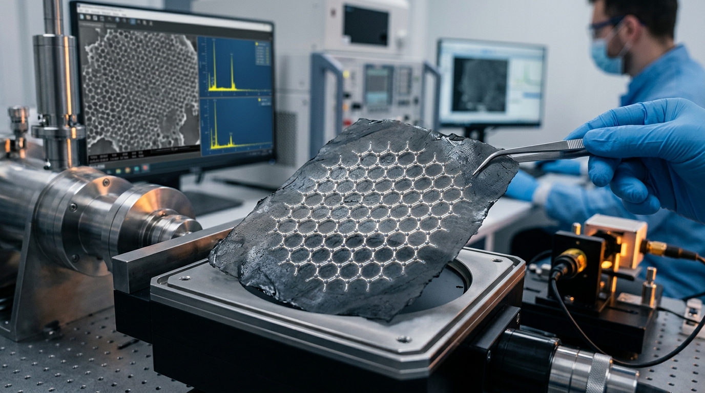
- Transmission Electron Microscopy (TEM) and Selected Area Electron Diffraction (SAED): High-resolution TEM (HRTEM) directly resolves individual atomic columns and sheet edges, allowing precise counting of the number of layers at the boundary. Hexagonal diffraction patterns reveal single-crystal structure versus polycrystalline domain misorientations.
DIY Realities vs. Verifiable Monolayer Production
The ubiquity of graphite powder and household chemical reagents has led to numerous informal attempts to produce graphene in non-laboratory settings. However, critical distinctions exist between verifiable atomic monolayers and coarse graphite powders:
- Multi-Layer Graphite Platelets vs. True Graphene: According to ISO standard ISO/TS 80004-13, a material is officially classified as graphene only if it has between 1 and 10 layers. Blending graphite powder in kitchen blenders or treating it with household chemicals yields bulk graphite nanoplatelets (GNPs) consisting of hundreds of layers, which lack the quantum confinement, high optical transparency, and exceptional carrier mobility of true monolayer graphene.
- Dispersion vs. Exfoliation: Mechanically breaking graphite down into fine dust in water creates a cloudy suspension that readily settles without surfactant stabilization. This is mechanical comminution (milling), not thermodynamic exfoliation.
- Characterization Barriers: Producing genuine graphene requires immediate access to micro-Raman spectroscopy or atomic force microscopy to verify that single layers have been produced rather than micro-graphite particulates.
Laboratory Safety and Risk Management
Graphene synthesis protocols involve hazardous chemical oxidizers, flammable gases, high-voltage discharges, and airborne nanomaterials that require specific safety protocols.
Chemical Hazard Management
- Exothermic Reactions in the Hummers Method: The addition of potassium permanganate to concentrated sulfuric acid forms dimanganese heptoxide (Mn2O7), a highly reactive, explosive intermediate that decomposes violently at temperatures above 55°C. Additions must be carried out slowly in an ice bath with continuous thermal monitoring inside a certified chemical fume hood.
- Corrosive Acid Waste: The oxidation and washing of graphene oxide generates large volumes of acidic wastewater containing heavy metal residues (manganese ions) that require dedicated chemical neutralization and hazardous waste segregation.
Thermal and High-Voltage Hazards
- CVD Tube Furnaces: Operating at 1,000°C with hydrogen and methane gas streams requires strict leak-checking protocols, active gas detection sensors, and dedicated exhaust burn boxes to prevent explosive atmospheric mixtures.
- Flash Joule Heating Equipment: FJH systems utilize high-capacity capacitor banks operating at elevated direct-current voltages (100V to 400V+), posing severe arc-flash and electrical shock risks. Systems must be enclosed with mechanical interlocks and high-speed automated discharge circuits.
Nanomaterial Inhalation and Handling
- Dry Powder Aerosolization: Dry graphene and reduced graphene oxide powders have extremely low bulk densities and readily form persistent airborne aerosols. Inhalation of these respirable carbon nanomaterials can cause pulmonary inflammation and micro-vascular stress analogous to other high-aspect-ratio particulates.
- Engineered Controls: All handling of dry graphene powders must take place inside a certified HEPA-filtered glovebox, ventilated biosafety cabinet, or dedicated chemical fume hood. Personnel should utilize NIOSH-approved N95 or P100 respirators and non-porous nitrile gloves to eliminate both inhalation and transdermal exposure routes.