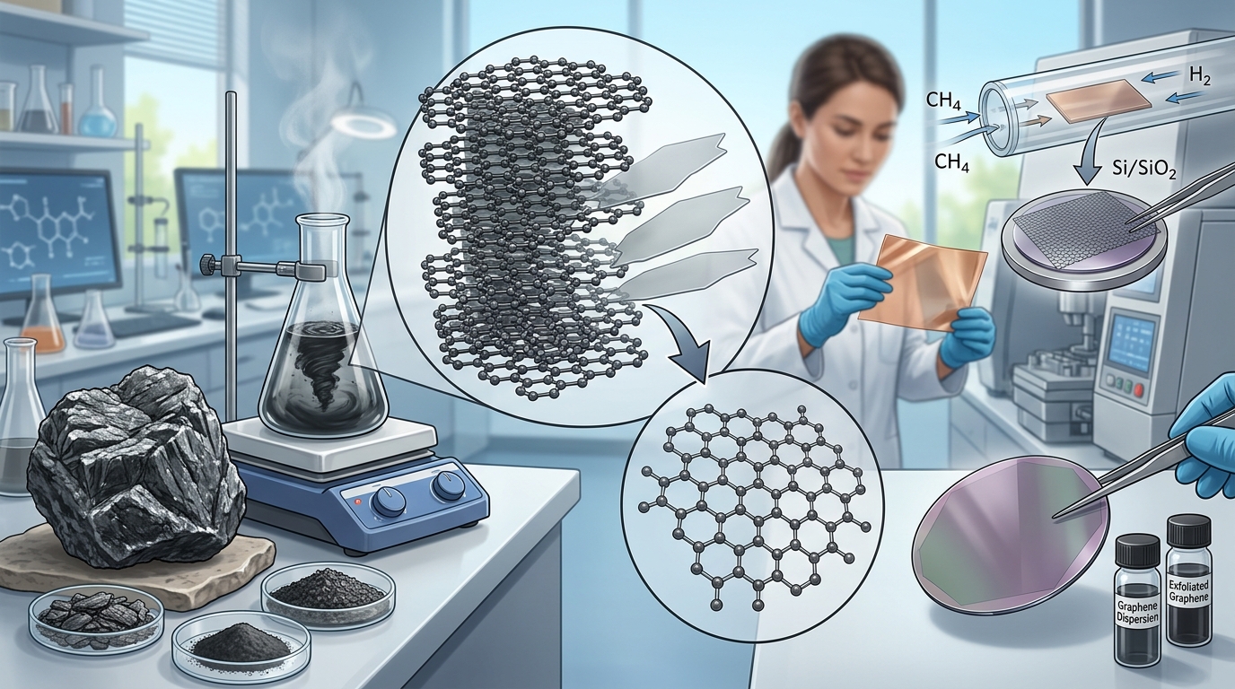
Methods for Producing Graphene from Graphite
Extracting graphene from naturally occurring or synthetic graphite requires separating individual atomically thin carbon sheets from a three-dimensional crystalline lattice. In bulk graphite, carbon atoms are arranged in two-dimensional, $sp^2$-hybridized planar networks held together by covalent $sigma$-bonds and delocalized $pi$-bonds. Between adjacent layers, however, the structure is bound exclusively by weak van der Waals interactions, with an interlayer separation ($d$-spacing) of approximately 0.335 nm and an interlayer binding energy on the order of 40 to 60 meV per carbon atom.
Top-down synthesis encompasses the suite of physical, chemical, and electrochemical processes designed to overcome this interplanar van der Waals attraction. The primary technical challenge across all methods for producing graphene from graphite is applying sufficient normal or shear stress to peel or push the layers apart without destroying the in-plane $sp^2$ carbon lattice or inducing irreversible structural agglomeration.
1. Micromechanical Cleavage (The Scotch Tape Method)
Discovered as a repeatable isolation technique in 2004, micromechanical cleavage relies on peel forces applied to the basal plane of highly oriented pyrolytic graphite (HOPG) or high-grade natural flake graphite using a visco-elastic adhesive medium, typically polyimide or acrylic tape.
Process Mechanism
- Adhesion: Bulk graphite is pressed onto the adhesive surface, establishing intimate contact with the outermost basal planes.
- Peeling: Peeling the tape applies a normal tensile stress that exceeds the interlayer van der Waals binding energy, pulling multi-layer flakes from the parent crystal.
- Repeated Cleavage: The adhered flakes are repeatedly folded and separated on fresh adhesive surfaces, progressively reducing layer count.
- Transfer: The thinned flakes are brought into contact with an oxidized silicon wafer (typically $text{SiO}_2$/Si with an oxide thickness of 90 nm or 285 nm for optical contrast). Van der Waals attraction between the graphene and the substrate allows the tape to be peeled away, leaving pristine single- and few-layer flakes behind.
Structural Integrity and Limitations
Micromechanical cleavage produces graphene with near-perfect crystallographic quality. The flakes exhibit negligible defect bands in Raman spectroscopy (a near-zero D-band intensity relative to the G-band), preserving intrinsic electron mobility exceeding $200,000text{ cm}^2/(text{V}cdottext{s})$ at low temperatures. However, the yield is miniscule (typically picograms to micrograms), the flake distribution across substrates is entirely stochastic, and manual identification via optical microscopy is labor-intensive. As a result, this method remains an analytical and fundamental research baseline rather than an industrial production route.
2. Liquid-Phase Exfoliation (LPE)
Liquid-phase exfoliation directly disperses bulk graphite powder into a liquid medium, using mechanical energy to cleave the layers while the liquid prevents the separated sheets from re-stacking.
Cavitation and Shear Mechanics
LPE relies on two primary mechanical pathways:
- Acoustic Cavitation (Ultrasonication): High-power tip sonication or ultrasonic baths generate microbubbles in the liquid. The violent collapse of these cavitation bubbles creates high-energy micro-jets and local shock waves that exert intense normal and shear forces on graphite particles, prying adjacent basal planes apart.
- High-Shear Fluid Dynamics: Rotor-stator mixers and microfluidization systems pump graphite dispersions through narrow gaps or micro-channels at high velocities. The resulting fluid shear rate (typically required to exceed $10^4text{ s}^{-1}$) peels graphene layers via viscous drag forces.
Solvent Matching and Surfactant Stabilization
Unstabilized graphene flakes suspended in liquids rapidly re-aggregate due to strong attractive inter-sheet van der Waals forces. To minimize the energetic cost of exfoliation, the surface energy of the solvent must closely match that of graphene (approximately $70text{ to }80text{ mJ/m}^2$).
Solvents such as N-Methyl-2-pyrrolidone (NMP), Dimethylformamide (DMF), and ortho-dichlorobenzene (DCB) satisfy these Hansen and Hildebrand solubility parameters, yielding stable, unfunctionalized graphene dispersions. However, because these solvents have high boiling points, high costs, and notable toxicity profiles, alternative water-surfactant systems are widely utilized.
In aqueous exfoliation, ionic surfactants (such as sodium dodecyl sulfate [SDS] or sodium cholate) or non-ionic block copolymers (such as Pluronic grades) adsorb onto the hydrophobic basal planes. The hydrophilic heads point outward into the water phase, creating electrostatic or steric repulsion barriers that keep the exfoliated few-layer flakes stably suspended.
3. Chemical Oxidation-Reduction (The Hummers Route)
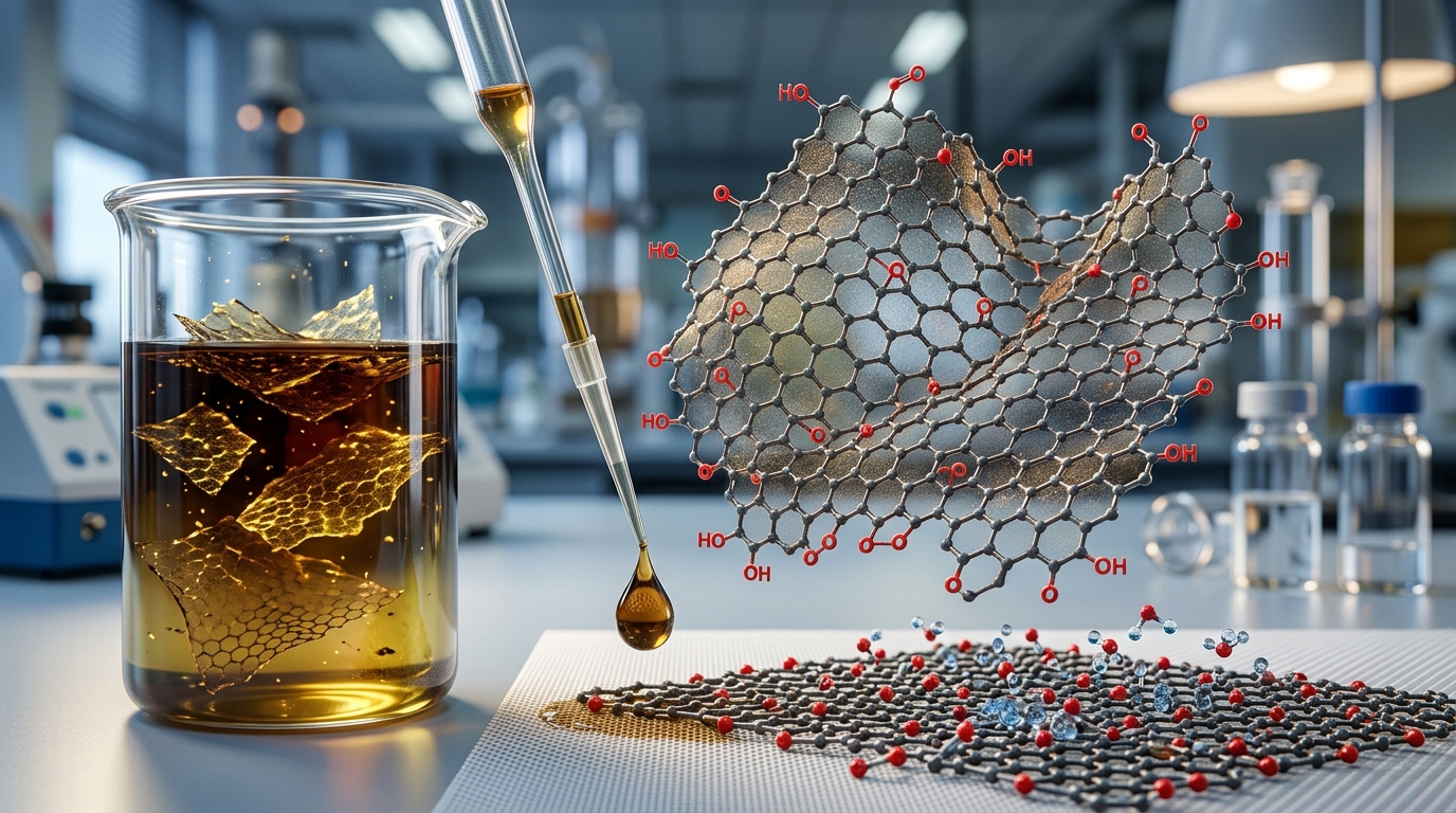
The chemical route breaks down graphite by severely disrupting its electronic and crystal lattice, turning it into a hydrophilic, highly exfoliated intermediate known as graphene oxide (GO), which is subsequently reduced back to reduced graphene oxide (rGO).
Oxidation Mechanism: Modified Hummers Method
Graphite flakes are treated with a strong mixture of concentrated sulfuric acid ($text{H}_2text{SO}_4$) and potassium permanganate ($text{KMnO}_4$), frequently modified by omitting sodium nitrate ($text{NaNO}_3$) to prevent toxic nitrogen dioxide emissions or adding phosphoric acid ($text{H}_3text{PO}_4$) to increase structural regularity (the Tour method).
- Acid Intercalation: Sulfuric acid intercalates into the graphite galleries, forming an initial graphite intercalation compound (GIC).
- Oxidative Functionalization: Active manganese oxide species attack the carbon lattice, covalently attaching oxygen-containing functional groups—predominantly epoxy ($-O-$) and hydroxyl ($-OH$) groups across the basal plane, along with carboxyl ($-COOH$) groups along the flake edges.
- Lattice Expansion: The introduction of these bulky functional groups expands the graphite interlayer spacing from $0.335text{ nm}$ to between $0.7text{ nm}$ and $1.2text{ nm}$, weakening the interlayer van der Waals bonding.
Exfoliation to Graphene Oxide
Because graphene oxide is heavily functionalized with hydrophilic polar groups, it readily hydrates in water. Gentle stirring or brief low-power bath sonication provides sufficient energy to achieve near-100% single-layer GO suspensions without requiring expensive high-boiling-point solvents.
Reduction Pathways to rGO
Because the extensive $sp^3$ oxidation network disrupts the conjugated $pi$-system, pristine GO is electrically insulating. To restore electrical and thermal conductivity, GO must undergo reduction to remove oxygen groups:
- Chemical Reduction: Utilizing reducing agents such as hydrazine monohydrate ($text{N}_2text{H}_4$), L-ascorbic acid (vitamin C), or sodium borohydride ($text{NaBH}_4$).
- Thermal Annealing: Rapidly heating dried GO powder above $800^circtext{C}$ in an inert or reducing atmosphere (argon, nitrogen, or hydrogen), which flash-vaporizes oxygen functionalities as $text{CO}$ and $text{CO}_2$ gases.
- Hydrothermal/Solvothermal Treatment: Subjecting GO aqueous suspensions to elevated temperatures ($150text{ to }200^circtext{C}$) under autogenous pressure in sealed autoclaves.
While reduction partially restores the $sp^2$ network, rGO retains significant structural point defects, vacancies, and residual oxygen (typically 5–15 atomic percent), which limits its carrier transport properties compared to pristine graphene.
4. Electrochemical Exfoliation Techniques
Electrochemical exfoliation is a high-yield, liquid-based approach that applies an electrical potential across graphite electrodes immersed in an electrolyte solution. This method is classified into anodic and cathodic routes depending on the polarity applied to the working graphite electrode.
Anodic Exfoliation
In anodic exfoliation, a positive bias (+3 to +10 V) is applied to a graphite working electrode in an acidic or neutral salt electrolyte (commonly aqueous ammonium sulfate, $(text{NH}_4)_2text{SO}_4$, or sulfuric acid).
- Anion Intercalation: The positive bias drives sulfate anions ($text{SO}_4^{2-}$) and water molecules directly into the graphite interlayers.
- Gas Evolution: Concurrently, electrochemical oxidation of water hydrolyzes and releases gaseous byproducts (primarily $text{O}_2$, $text{SO}_2$, and trace $text{CO}_2$) within the confined galleries.
- Expansion and Cleavage: The internal gas pressure forces the graphite lattice to expand rapidly, overcoming interplanar bonds and producing few-layer graphene flakes with low-to-moderate oxidation levels within minutes.
Cathodic Exfoliation
In cathodic exfoliation, a negative bias is applied to the graphite electrode, typically immersed in organic solvents containing large quaternary ammonium cations (such as tetrabutylammonium, $text{TBA}^+$) or lithium salts.
Because the graphite acts as a cathode, oxidative damage is virtually eliminated. Positively charged cations intercalate into the negative galleries along with solvent molecules. Applying high potentials or introducing co-solvents leads to radical decomposition and solvent expansion, yielding unoxidized, pristine-like few-layer graphene flakes, albeit generally at lower production rates than anodic routes.
5. Mechanochemical and Specialized Top-Down Routes
Mechanochemical Ball Milling
Ball milling uses high-energy kinetic collisions from steel or ceramic balls inside a rotating or vibrating jar to pulverize graphite. When operated dry, uninhibited vertical impact forces fracture the carbon basal planes into amorphous carbon nanoparticles. However, under wet shear conditions with stabilizing additives (e.g., dry ice/solid $text{CO}_2$, ionic liquids, or aqueous surfactants), the balls slide over the graphite surfaces. This delivers planar shear forces that cleanly exfoliate graphene sheets while edge-functionalizing the resulting flakes without degrading the internal basal plane.
Supercritical Fluid (SCF) Exfoliation
Supercritical fluids, most notably supercritical carbon dioxide ($text{scCO}_2$), exhibit gas-like mass transport properties combined with liquid-like solvating power. Operating above the critical point ($T_c = 31.1^circtext{C}$, $P_c = 7.39text{ MPa}$), $text{scCO}_2$ easily diffuses into the narrow galleries of graphite. When the system undergoes rapid depressurization, the expanding fluid forces the graphite layers apart instantly. This route is entirely solvent-free and leaves zero liquid chemical residues on the final powder.
Comparison of Graphite-to-Graphene Production Methods
| Method | Typical Flake Size | Layer Distribution | Defect Density ($I_D/I_G$) | Scalability / Throughput | Primary Structural Characteristic |
|---|---|---|---|---|---|
| Micromechanical Cleavage | 10 – 100 μm | Single-layer (monolayer) | < 0.05 (Near zero) | None (Laboratory scale only) | Pristine, defect-free $sp^2$ crystal lattice |
| Liquid-Phase Exfoliation (LPE) | 200 nm – 2 μm | 1 to 10 layers (Few-layer dominant) | 0.1 – 0.4 (Low) | Moderate to High (Continuous liquid processing) | Retains high pristine character; small lateral dimensions |
| Modified Hummers (GO & rGO) | 1 – 50 μm | > 90% Single-layer (as GO) | 0.9 – 1.8 (High) | Very High (Metric ton bulk capability) | Disrupted lattice; high content of residual oxygen and vacancies |
| Electrochemical Exfoliation | 1 – 20 μm | 1 to 5 layers | 0.1 – 0.6 (Low to moderate) | High (Fast reaction kinetics) | Large lateral flake size with tunable edge/basal oxidation |
| Mechanochemical Ball Milling | 100 nm – 5 μm | Few- to multi-layer (3 to 10+ layers) | 0.3 – 1.0 (Moderate) | Very High (Industrial solids handling) | Edge-functionalized; risk of basal plane breakage if unmoderated |
Process Selection Criteria for Material Specifications
Selecting among the various methods for producing graphene from graphite requires balancing structural purity against processing costs, throughput volume, and final morphology:
- High-Conductivity Networks and Inks: Liquid-phase exfoliation and cathodic electrochemical exfoliation yield low-defect graphene flakes that preserve the unoxidized $pi$-conjugation necessary for high electrical and thermal conductivity, making them suitable for printed electronics and EMI shielding formulations.
- Bulk Composites and Energy Storage: The chemical oxidation route (Hummers method yielding GO/rGO) remains the standard for polymer reinforcement, battery anode additives, and supercapacitor electrodes. The extensive oxygen-containing functional groups facilitate strong chemical cross-linking with polymer matrices and promote rapid wettability in polar battery electrolytes.
- High-Volume Industrial Coatings: Mechanochemical wet ball milling and anodic electrochemical exfoliation offer pragmatic routes when large volumes of multi-layer or edge-functionalized graphene are required without the extreme acidic waste footprint of the full Hummers oxidation process.