How to Turn Graphite into Graphene?
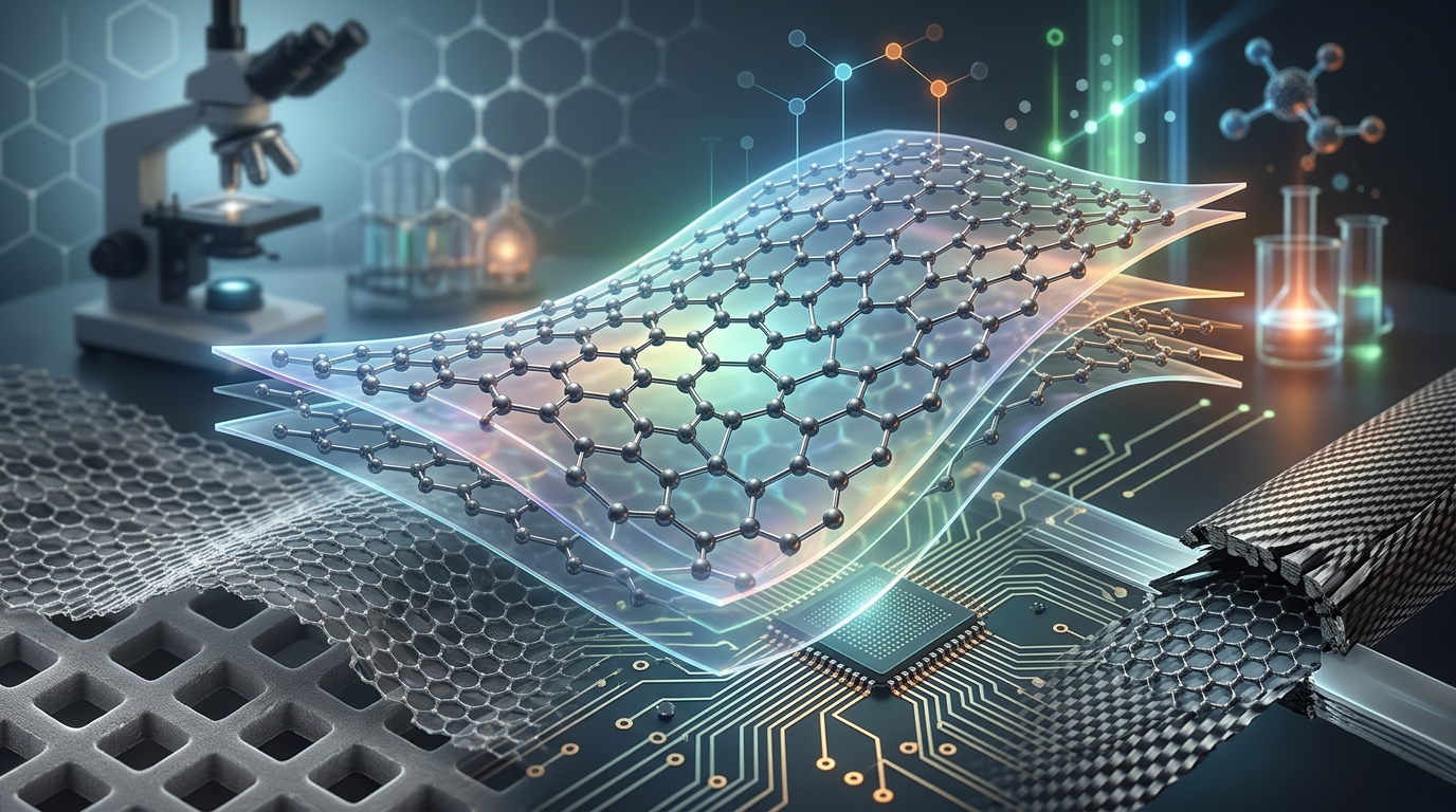
Converting bulk graphite into graphene is achieved through top-down exfoliation. Bulk graphite consists of millions of stacked, two-dimensional carbon sheets. To transform graphite into isolated single-layer or few-layer graphene, processing methods must apply sufficient external energy—mechanical, chemical, or electrical—to overcome the interlayer bonds holding the sheets together without destroying their hexagonal carbon lattice.
The Core Principle: Overcoming Interlayer Van der Waals Forces
Graphite is an allotrope of carbon where atoms form planar, hexagonal networks through robust $sp^2$ covalent bonds with a bond length of approximately 0.142 nm. These individual layers are known as graphene. In three-dimensional graphite crystals, these sheets stack vertically with an interlayer spacing of approximately 0.335 nm.
While the in-plane covalent bonds are among the strongest chemical bonds known, the sheets are bound to one another only by weak interlayer Van der Waals forces, exhibiting an interlayer binding energy of roughly 40 to 60 meV per carbon atom. Turning graphite into graphene requires delivering targeted energy to shear or expand these sheets apart while minimizing damage to the in-plane carbon lattice.
1. Mechanical Exfoliation Techniques
Mechanical exfoliation applies direct physical forces to cleave graphite crystals parallel to their basal planes.
Micromechanical Cleavage (The Scotch Tape Method)
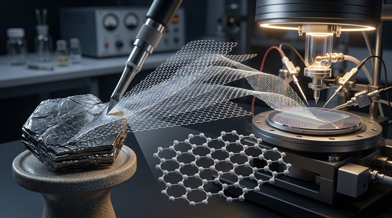
Historically demonstrated in 2004 by Andre Geim and Konstantin Novoselov, micromechanical cleavage was the first method used to isolate single-layer graphene from highly oriented pyrolytic graphite (HOPG). The process works through basic physical adhesion:
- Adhesive tape is pressed onto bulk graphite flakes.
- When peeled away, the normal peel force overcomes the weak Van der Waals interactions, pulling off multi-layer graphite films.
- The tape is folded and peeled repeatedly against fresh adhesive surfaces to split the flakes thinner.
- The thinned flakes are pressed onto an oxidized silicon wafer ($SiO_2/Si$), transferring pristine single- and few-layer graphene flakes to the substrate.
Use Case: This method produces pristine, defect-free graphene crystals ideal for fundamental physics research, but it cannot be scaled for industrial production.
High-Energy Ball Milling
Ball milling uses rotating or vibrating chambers filled with grinding media (such as stainless steel or zirconia balls) to exert shear and impact forces on bulk graphite powder.
- Dry Ball Milling: High-impact collisions frequently fracture the in-plane carbon bonds, producing fragmented, highly defective graphite flakes with functionalized edges rather than broad single sheets.
- Wet/Liquid-Assisted Milling: Incorporating lubricating milling agents, solvents, or surfactants redirects mechanical energy toward lateral shear stress rather than vertical impact. This shears graphite layers apart along their planes, generating larger aspect-ratio graphene nanoplatelets with significantly fewer basal-plane defects.
2. Liquid-Phase Exfoliation (LPE)
Liquid-phase exfoliation (LPE) disperses graphite powder into a liquid medium and uses fluid dynamics to separate the sheets. This approach is widely used for producing moderate-to-high volumes of few-layer graphene dispersions.
Ultrasonic Cavitation (Sonication)
In this technique, graphite is suspended in a specialized liquid and subjected to high-frequency acoustic waves (tip or bath sonication):
- Acoustic waves induce acoustic cavitation—the formation, growth, and violent collapse of microscopic bubbles.
- The localized microjets and high-pressure shockwaves generated during bubble collapse generate intense shear stress along the graphite basal planes, peeling sheets off the bulk crystals.
- To prevent the peeled graphene sheets from instantly re-aggregating, the surface energy of the solvent must closely match the surface energy of graphene ($ ext{approx. } 70 ext{–}80 ext{ mJ/m}^2$). Solvents such as N-methyl-2-pyrrolidone (NMP), N,N-dimethylformamide (DMF), and ortho-dichlorobenzene (DCB) are effective standards.
- Alternatively, graphite can be exfoliated in water by adding ionic or non-ionic surfactants (such as sodium cholate or sodium dodecyl sulfate) that adsorb onto the exfoliated sheets and prevent re-stacking via electrostatic or steric repulsion.
High-Shear Fluid Exfoliation
High-shear mixing forces graphite slurries through narrow gaps or microfluidic channels at high flow velocities. The resulting hydrodynamic shear rates (typically exceeding $10^4 ext{ s}^{-1}$) separate the graphite layers without relying on ultrasonic cavitation, making continuous, high-volume production feasible.
3. Chemical Oxidation and Reduction (The Hummers Route)
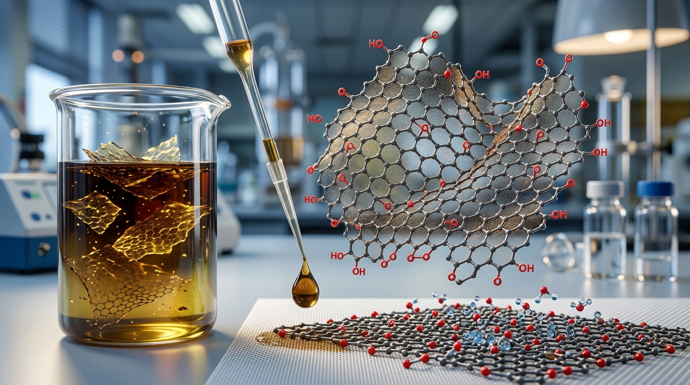
The chemical route converts graphite into an intermediate material called Graphene Oxide (GO) before chemically or thermally reducing it into reduced Graphene Oxide (rGO). This method is the most widely adopted chemical approach for producing large volumes of functionalized graphene.
Step 1: Oxidation (Modified Hummers Method)
Graphite powder is mixed with strong oxidizing agents—typically potassium permanganate ($KMnO_4$), concentrated sulfuric acid ($H_2SO_4$), and sodium nitrate ($NaNO_3$) or phosphoric acid ($H_3PO_4$):
- The chemical reagents intercalate into the graphite galleries, oxidizing the carbon planes.
- Oxygen-containing functional groups (hydroxyl, epoxide, carbonyl, and carboxyl groups) covalently attach to the basal planes and edges.
- These functional groups increase the interlayer spacing from 0.335 nm to over 0.7–1.0 nm and render the sheets hydrophilic.
Step 2: Exfoliation into Graphene Oxide (GO)
Because the interlayer spacing is significantly widened and the forces weakened, mild mechanical agitation or short-duration sonication in water readily exfoliates the material into single-layer Graphene Oxide sheets suspended in solution.
Step 3: Reduction to rGO
Because oxidation disrupts the $sp^2$ conjugate network—turning the material into an electrical insulator—the oxygen groups must be removed to restore electrical and thermal conductivity:
- Chemical Reduction: Adding reducing agents such as hydrazine monohydrate, sodium borohydride, or ascorbic acid (Vitamin C).
- Thermal Reduction: Rapid heating in an inert or reducing atmosphere (argon/hydrogen) at temperatures between 400°C and 1100°C, causing sudden gas release ($CO_2$, $H_2O$) that further exfoliates and deoxygenates the sheets.
- Hydrothermal Reduction: Processing the GO solution under high temperature and autogenous pressure in a sealed autoclave.
Note: Reduced graphene oxide retains residual oxygen defects and vacancy clusters; its electrical conductivity is lower than that of pristine graphene.
4. Electrochemical Exfoliation
Electrochemical exfoliation uses electrical potential to drive ions from an electrolyte between the graphite layers, causing the graphite to swell and detach.
- Anodic Exfoliation: Bulk graphite serves as the working anode in an aqueous salt electrolyte (e.g., $(NH_4)_2SO_4$). A positive voltage drives sulfate anions ($SO_4^{2-}$) into the graphite galleries. Simultaneously, electrolysis of water generates localized oxygen and sulfur dioxide gases, expanding the lattice and cleanly stripping off few-layer graphene flakes with low defect levels.
- Cathodic Exfoliation: Graphite serves as the cathode, driven by negative bias. Cations (such as lithium or quaternary ammonium ions) intercalate into the graphite. While it requires organic solvents and air-sensitive conditions, cathodic exfoliation produces almost no oxidative defects on the carbon plane.
5. Advanced and Emerging Exfoliation Technologies
Flash Joule Heating (FJH)
Flash Joule heating passes an ultrafast, high-voltage electrical pulse through carbon materials (including low-grade graphite, carbon black, or organic waste) for 10 to 100 milliseconds. The rapid temperature rise ($>3000 ext{ K}$) causes instantaneous structural rearrangement, breaking intersheet bonds and forming turbostratic graphene—a configuration where adjacent sheets lack rotational alignment, making them easy to separate without chemical solvents.
Supercritical Fluid Exfoliation
Using fluids at temperatures and pressures past their thermodynamic critical point (such as supercritical carbon dioxide, $scCO_2$), fluid molecules diffuse deeply into graphite galleries due to their zero surface tension and gas-like diffusivity. Rapid depressurization causes the fluid inside the galleries to rapidly expand, overcoming the Van der Waals forces and splitting the graphite into thin platelets.
Graphite-to-Graphene Method Comparison
| Conversion Method | Flake Quality / Lattice Integrity | Layer Yield (Single Layer) | Scalability | Production Cost | Defect Density ($I_D/I_G$) |
|---|---|---|---|---|---|
| Scotch Tape (Cleavage) | Pristine ($sp^2$ intact) | Very Low (isolated flakes) | None (Manual) | Low (Labor Intensive) | Extremely Low ($< 0.05$) |
| Liquid-Phase Exfoliation | High (Minimal basal defects) | Low to Moderate | High | Moderate | Low ($0.1 ext{–}0.3$) |
| Hummers Route (GO / rGO) | Moderate (Disrupted lattice) | Very High ($> 90%$) | Very High | Low to Moderate | High ($> 1.0$) |
| Electrochemical Exfoliation | High to Moderate | Moderate to High | High | Low | Low to Moderate ($0.2 ext{–}0.6$) |
| Wet Ball Milling | Moderate (Edge functionalized) | Low to Moderate | High | Low | Moderate ($0.4 ext{–}0.8$) |
| Flash Joule Heating | High (Turbostratic) | High | High | Low to Moderate | Very Low ($< 0.1$) |
Characterization: Verifying Successful Conversion
To confirm that bulk graphite has been successfully converted into single-layer or few-layer graphene, researchers rely on three primary analytical techniques:
- Raman Spectroscopy: The primary tool for assessing layer count and structural defects. It evaluates the D band (~1350 cm$^{-1}$, indicating structural defects), the G band (~1580 cm$^{-1}$, in-plane $sp^2$ vibration), and the 2D band (~2700 cm$^{-1}$). A sharp, symmetric 2D band with an intensity ratio of $I_{2D}/I_G > 2$ indicates single-layer pristine graphene.
- Atomic Force Microscopy (AFM): Accurately measures the physical step-height of deposited flakes on flat substrates. A measured thickness of 0.35 to 0.8 nm indicates single-layer graphene (accounting for instrumental offsets and surface adsorbates).
- Transmission Electron Microscopy (TEM): High-resolution TEM (HRTEM) and Selected Area Electron Diffraction (SAED) verify the hexagonal crystal symmetry and allow direct counting of sheet edges to determine layer numbers.
Safety Considerations and Scalability Realities
Transforming graphite into graphene in production environments involves specific technical trade-offs and chemical hazards:
- Chemical Hazards in Oxidation: The modified Hummers method involves strongly exothermic reactions upon adding potassium permanganate to concentrated sulfuric acid, which can trigger thermal runaways. It also carries the risk of forming unstable manganese heptoxide ($Mn_2O_7$), requiring continuous temperature control and precise reagent feeding.
- Nanoparticle Handling: Dry graphene powders have low bulk densities and readily aerosolize. Inhalation of dry 2D carbon nanomaterials poses potential respiratory hazards, requiring the use of HEPA-filtered gloveboxes, fume hoods, and appropriate respirators.
- Quality vs. Quantity Trade-offs: Industrial scalability often comes at the cost of structural quality. Pristine mechanical cleavage yields exceptional quality but negligible quantity. Conversely, the Hummers method produces metric tons of material, but the resulting rGO retains structural defects and lower electrical conductivity, making it better suited for composite reinforcement and energy storage than high-frequency electronics.