Graphene Sheet
A single-atom-thick layer of carbon atoms densely packed into a two-dimensional honeycomb crystal lattice defines a graphene sheet. First isolated by Andre Geim and Konstantin Novoselov in 2004 using micromechanical cleavage, this fundamental carbon structure serves as the basic building block for other graphitic materials, including zero-dimensional fullerenes, one-dimensional carbon nanotubes, and three-dimensional stacked graphite.
Understanding what a graphene sheet is requires distinguishing between continuous, macroscopic planar films and fragmented micro-platelets. While colloidal dispersions of tiny flakes are often utilized as bulk additives, a true continuous graphene sheet is a macroscopic, continuous two-dimensional crystal. These sheets possess an extraordinary combination of electrical mobility, mechanical strength, thermal conductivity, and optical transparency that stems directly from their atomic architecture.
Atomic Architecture and Chemical Bonding
The remarkable behavior of a graphene sheet originates in its electronic configuration. Each carbon atom possesses four valence electrons. In a graphene sheet, three of these electrons hybridize into planar $sp^2$ orbitals, forming strong covalent sigma (σ) bonds with three neighboring carbon atoms. These bonds have a length of roughly 0.142 nanometers and provide the crystal lattice with exceptional in-plane mechanical integrity.
The fourth valence electron occupies an out-of-plane $p_z$ orbital. Neighboring $p_z$ orbitals overlap across the entire plane to create a delocalized network of pi (π) and pi-star (π*) bands. This continuous electron cloud facilitates ballistic electron transport, allowing charge carriers to travel macroscopic distances without experiencing the phase-destroying scattering common in conventional metals and semiconductors.
Because the valence and conduction bands intersect at six discrete points within the Brillouin zone known as Dirac points, graphene behaves as a zero-bandgap semimetal. Near these crossing points, the energy-momentum dispersion relation is linear rather than parabolic. As a result, electrons and holes in a graphene sheet behave as massless Dirac fermions, moving at an effective Fermi velocity of approximately $10^6$ meters per second.
Intrinsic Material Properties of Pristine Sheets
When evaluated in an idealized, defect-free state under controlled laboratory conditions, individual graphene sheets exhibit extreme physical values:
- Mechanical Strength: A pristine monolayer possesses an intrinsic tensile strength of roughly 130 gigapascals and an in-plane Young's modulus of 1 terapascal. This makes an individual atomic sheet one of the strongest materials ever measured in terms of bond energy per unit area.
- Thermal Conductivity: In-plane thermal transport in suspended pristine sheets is dominated by acoustic phonons, yielding thermal conductivity values ranging from 3,000 to 5,000 watts per meter-kelvin at room temperature.
- Electrical Carrier Mobility: Suspended, defect-free sheets have demonstrated electron mobilities exceeding 200,000 square centimeters per volt-second at low temperatures, far surpassing single-crystal silicon.
- Optical Transmittance: Despite being only one atom thick, a single sheet absorbs approximately 2.29% of incident white light, meaning it maintains a 97.7% optical transparency across the visible spectrum.
- Impermeability: The high electron density of the aromatic rings creates a geometric barrier impenetrable to standard gas molecules under ambient conditions, including helium.
Manufacturing Continuous Graphene Sheets
Translating atomic-scale properties into usable industrial components depends on the synthesis route. Different manufacturing processes yield sheets of drastically varying structural quality, domain size, and defect density.
Chemical Vapor Deposition (CVD)
The standard industrial approach for producing continuous, large-area sheets is catalytic chemical vapor deposition. In this thermal process, a hydrocarbon precursor gas (such as methane) is introduced into a furnace containing a transition metal catalytic substrate, typically high-purity copper or nickel foil, heated to roughly 1,000 degrees Celsius.
On copper, which has exceptionally low carbon solubility, the growth is self-limiting: methane decomposes catalytically on the metal surface, and growth halts once a single atomic monolayer covers the copper grain. On nickel, carbon dissolves into the bulk metal at elevated temperatures and precipitates back to the surface during cooling, often resulting in heterogeneous mixtures of single-layer, bilayer, and multilayer domains unless cooling rates are rigorously controlled.
Epitaxial Growth on Silicon Carbide
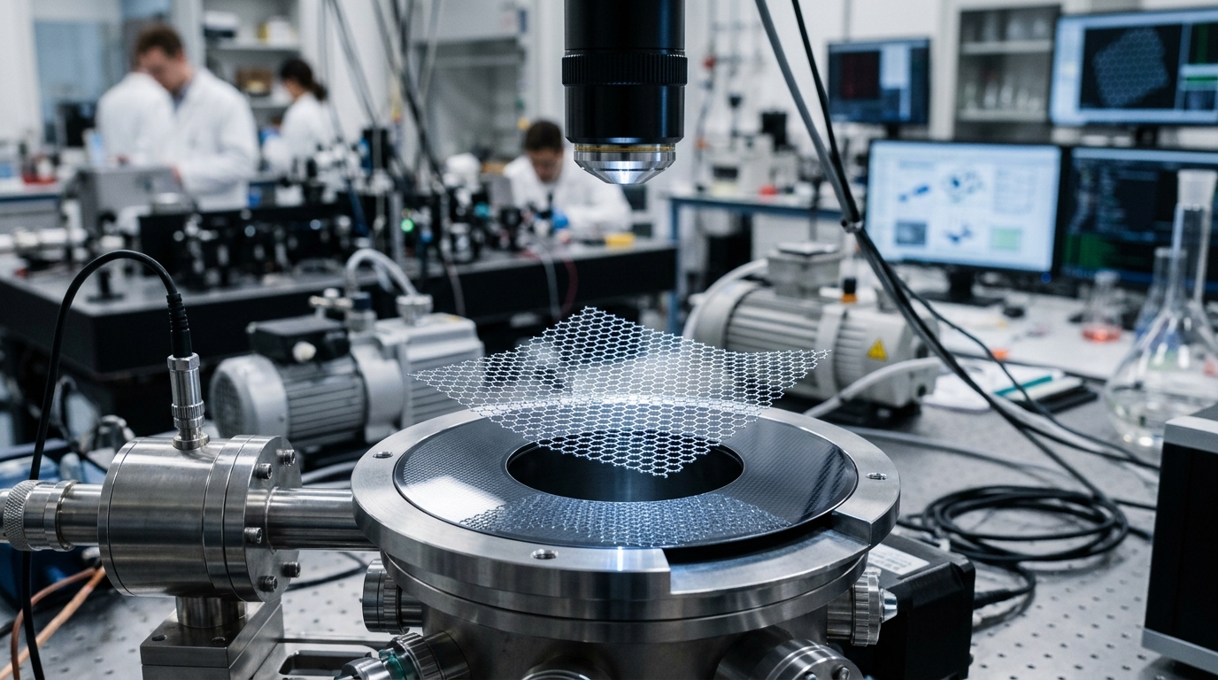
High-frequency electronic applications often rely on the thermal decomposition of silicon carbide (SiC) wafers. When heated to high temperatures in an ultra-high vacuum or argon environment, silicon atoms sublimate from the surface, leaving behind excess carbon that rearranges into epitaxial graphene sheets. This method yields uniform, wafer-scale films directly on an insulating or semi-insulating substrate, bypassing the destructive handling steps required with metal catalysts.
Liquid-Phase Exfoliation and Reduction
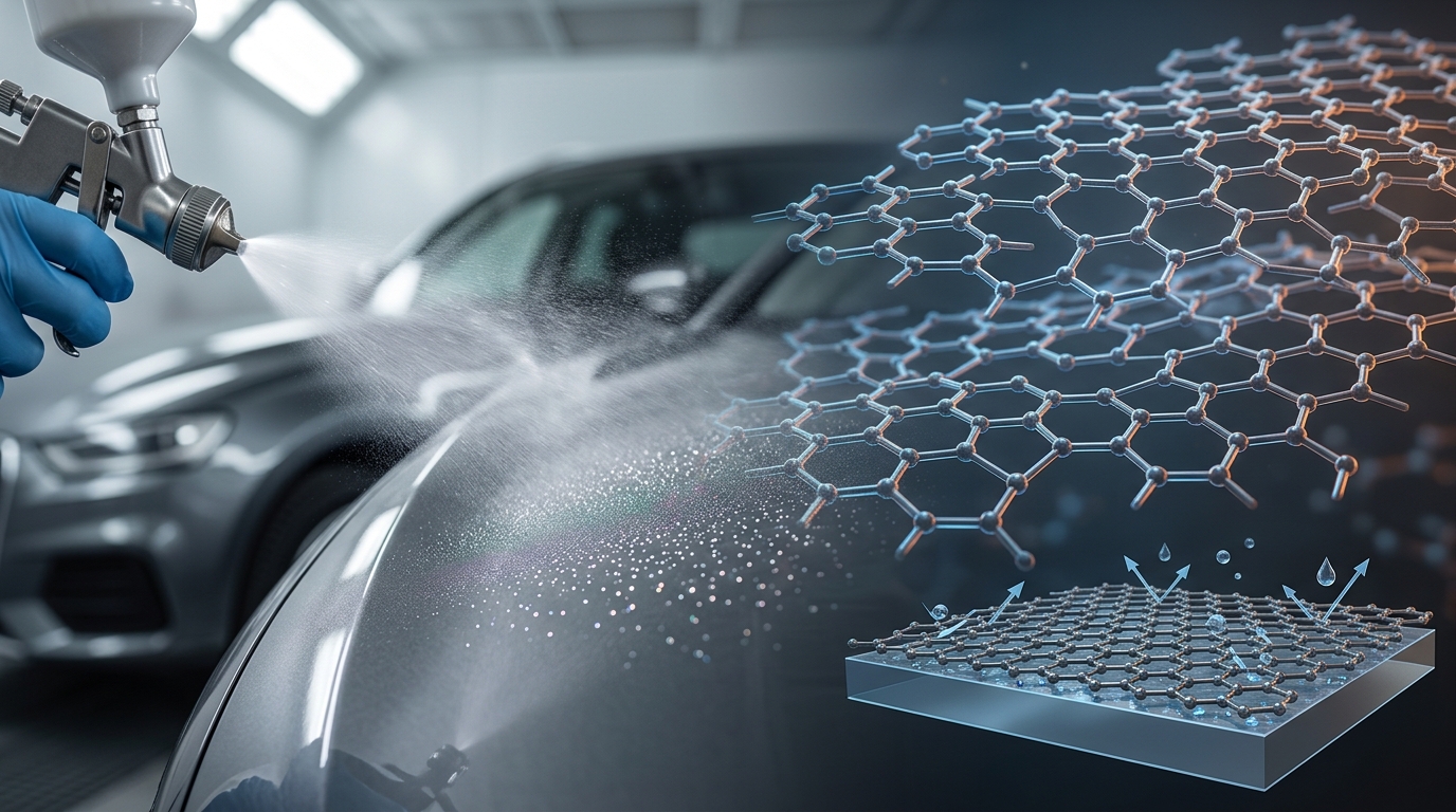
Liquid-phase exfoliation involves shearing natural graphite in specialized solvent baths or chemically oxidizing graphite into graphene oxide (GO), which readily disperses in water. Subsequent thermal or chemical reduction produces reduced graphene oxide (rGO) sheets. Although cost-effective and scalable for coatings and bulk composites, rGO sheets contain substantial vacancy defects, residual oxygen functional groups, and truncated lateral dimensions that degrade electrical conductivity and mechanical modulus compared to CVD-grown sheets.
The Transfer Problem: Moving the Sheet to a Substrate
For CVD-grown graphene, synthesis is only half the engineering challenge. Because the catalytic metal substrate is electrically conductive and optically opaque, the graphene sheet must be transferred onto a target substrate—such as silicon dioxide, quartz, or flexible polyethylene terephthalate (PET)—without introducing physical defects.
The traditional wet-transfer method employs a temporary polymeric transfer layer, typically poly(methyl methacrylate) (PMMA), spin-coated onto the top surface of the graphene. The underlying metal foil is chemically etched away in an acid or persulfate bath, leaving the PMMA/graphene membrane floating on the liquid surface. The film is mechanically scooped onto the target substrate, dried, and the PMMA is dissolved with acetone.
Despite its widespread laboratory use, wet transfer introduces distinct performance bottlenecks:
- Polymer Residues: Trace organic residues remain on the sheet surface, causing unintended chemical doping and increased carrier scattering.
- Wrinkling and Cracking: Surface tension forces during drying cause micro-tears, folds, and delamination pockets across the sheet.
- Metallic Contamination: Chemical etchants can leave sub-nanometer transition-metal impurities, which degrades performance in semiconductor applications.
Alternative dry-transfer and roll-to-roll mechanical delamination methods use thermal release tapes or water-mediated bubbling transfer to strip the sheet nondestructively, offering cleaner interfaces for industrial manufacturing.
Defects and Structural Realities
Real-world macroscopic sheets rarely match theoretical predictions because they are polycrystalline. During CVD growth, separate graphene nucleation islands grow until they coalesce, forming irregular grain boundaries. These boundaries consist of non-hexagonal carbon rings (such as pentagon-heptagon Stone-Wales pairs) that induce grain boundary scattering, which reduces mechanical fracture limits and depresses electronic mobility.
Point vacancies, lattice substitutions, and structural ripples also impact performance. Substrate roughness introduces local strain variations, and airborne hydrocarbons rapidly adsorb onto the surface when exposed to the atmosphere, shifting the Fermi level through p-type doping within minutes of ambient exposure.
How Continuous Sheets Differ from Other Graphene Forms
| Feature | Continuous CVD Graphene Sheet | Reduced Graphene Oxide (rGO) | Graphene Nanoplatelets (GNPs) |
|---|---|---|---|
| Primary Morphology | Unbroken 2D single-layer film | Fragmented, oxidized 2D flakes | Thick stacks (5 to 30+ layers) |
| Lateral Area | Centimeters to continuous rolls | Sub-micron to tens of microns | 1 to 50 microns |
| Typical Sheet Resistance | 200 to 1,000 Ω/sq (undoped) | 10,000 to 1,000,000+ Ω/sq | N/A (Used as bulk additive) |
| Optical Transparency | ~97.7% per layer | Variable (Brownish/Semi-transparent) | Opaque in bulk form |
| Common Uses | RF electronics, photonics, sensors | Water filtration, conductive inks | Polymer reinforcement, battery pastes |
Demonstrated and Practical Applications
High-Frequency Electronics and RF Transistors
Because pristine graphene lacks an intrinsic bandgap, digital logic transistors made from it cannot be switched completely off, limiting its utility in conventional computer microprocessors. However, this absence of a bandgap does not preclude high-frequency analog devices. Continuous sheets are used in radio-frequency (RF) transistors, frequency multipliers, and low-noise amplifiers, taking advantage of ultra-high carrier velocity to process signals in the gigahertz and terahertz domains.
Optoelectronics and Photodetectors
Graphene sheets can absorb photons across an extraordinarily broad spectral range, extending from ultraviolet through visible to far-infrared and terahertz frequencies. Because optical absorption transitions occur via interband transitions of Dirac fermions, continuous sheets serve as ultrafast photodetectors, optical modulators in fiber-optic communications, and transparent conductive electrodes in specialized displays where mechanical flexibility is critical.
Thermal Dissipation Layers
Stacked and thick laminated graphene sheets serve as high-efficiency heat spreaders in compact electronics. By aligning the basal planes along the lateral direction, heat generated by dense processing units can be conducted laterally away from thermal hotspots. This thermal heat spreading architecture prevents device throttling without the weight penalty of thick copper plates.
Impermeable Barriers and Molecular Sieving
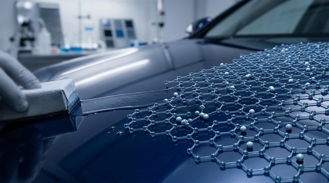
A continuous, defect-free graphene sheet is an absolute barrier to all atomic species under standard conditions. Coated onto metals, it provides an ultra-thin barrier against chemical corrosion and oxidation. Conversely, when nanometer-sized pores are intentionally introduced via ion bombardment or chemical etching, a single sheet functions as an atomic-scale molecular sieve, enabling low-energy water desalination and specialized gas separations.
Biochemical and Gas Sensing
Because every single atom in a monolayer graphene sheet is directly exposed to its surrounding environment, any gas molecule or biomolecule that adsorbs onto the surface alters the local electrical conductivity. Functionalized graphene sheets fabricated into field-effect sensor configurations can detect trace concentrations of target proteins, environmental gases, or DNA fragments with high signal-to-noise ratios.
Quality Characterization and Evaluation Criteria
In research and manufacturing environments, engineers assess the quality of a graphene sheet using several non-destructive analytical techniques:
- Raman Spectroscopy: Raman spectroscopy is the definitive diagnostic method for carbon nanomaterials. A pristine monolayer sheet displays two prominent features: the G-band (around 1580 cm⁻¹) representing in-plane carbon vibration, and the 2D-band (around 2690 cm⁻¹). A sharp, symmetric 2D peak with an intensity ratio of $I_{2D}/I_G > 2$ confirms a single monolayer. The presence of a D-band (around 1350 cm⁻¹) indicates structural defects, vacancies, or grain boundaries.
- Sheet Resistance Measurements: Evaluated using four-point probe or eddy current testing methods, sheet resistance (measured in ohms per square) indicates the electrical continuity of the film. Lower resistance values at high optical transmittance indicate fewer tears and lower transfer contamination.
- Atomic Force Microscopy (AFM): AFM provides height profiles of the transferred film to confirm single-layer thickness (approximately 0.34 to 0.4 nanometers on flat substrates) and reveals surface contamination, tears, or folds.
- Hall Effect Measurements: This technique quantifies charge carrier concentration and Hall mobility, confirming whether the sheet is dominated by electrons or holes and evaluating the impact of ambient doping.
Engineering Tradeoffs and Selection Principles
Deploying a graphene sheet requires balancing performance benefits against real-world manufacturing constraints. CVD-grown sheets provide high structural fidelity, transparency, and mobility, but are constrained by the cost and physical complexity of substrate transfer. Liquid-exfoliated sheets and graphene oxide variants provide scalable production, yet trade away crystal quality, electrical performance, and optical clarity.
Selecting the appropriate form depends on whether the device demands the intrinsic quantum transport of an unbroken crystal lattice, or simply benefits from the percolation conductivity, barrier behavior, and thermal transport of fragmented two-dimensional carbon.